
|
603-630-5658
|
|
tinypontoonboats@gmail.com
|

|
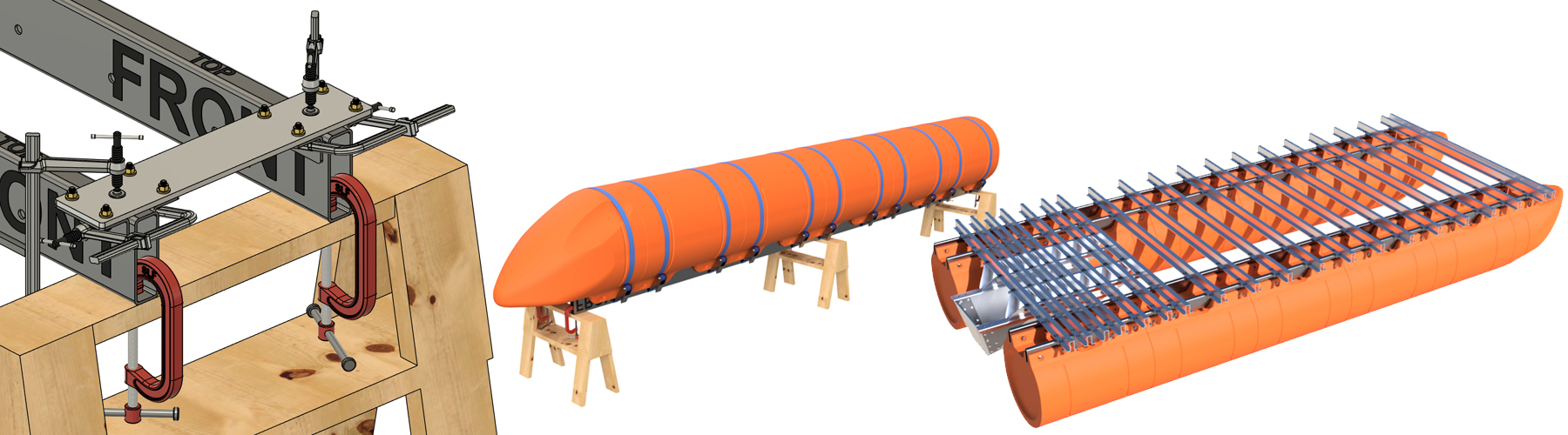
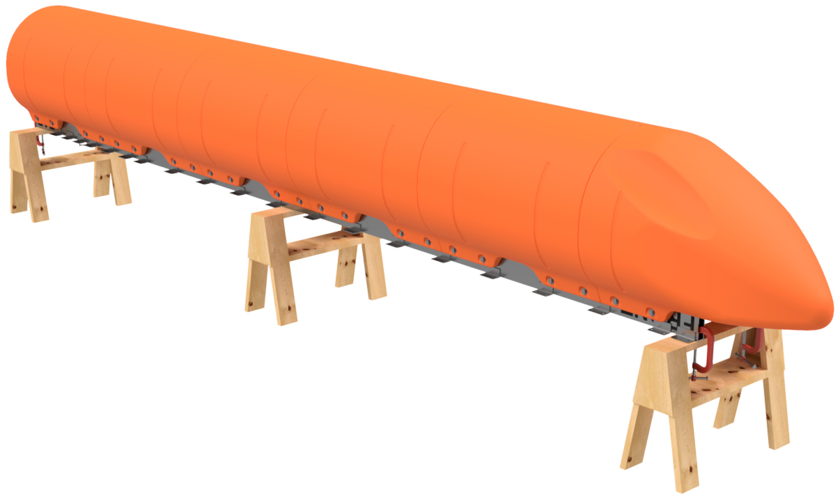
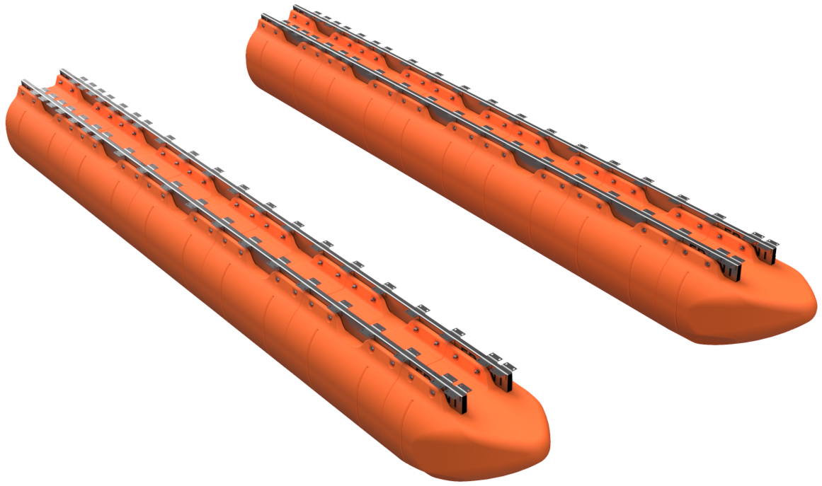
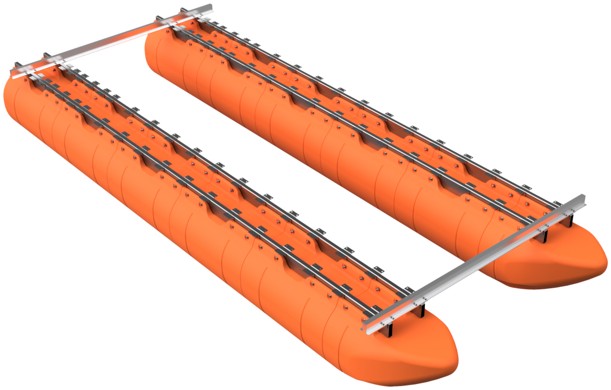
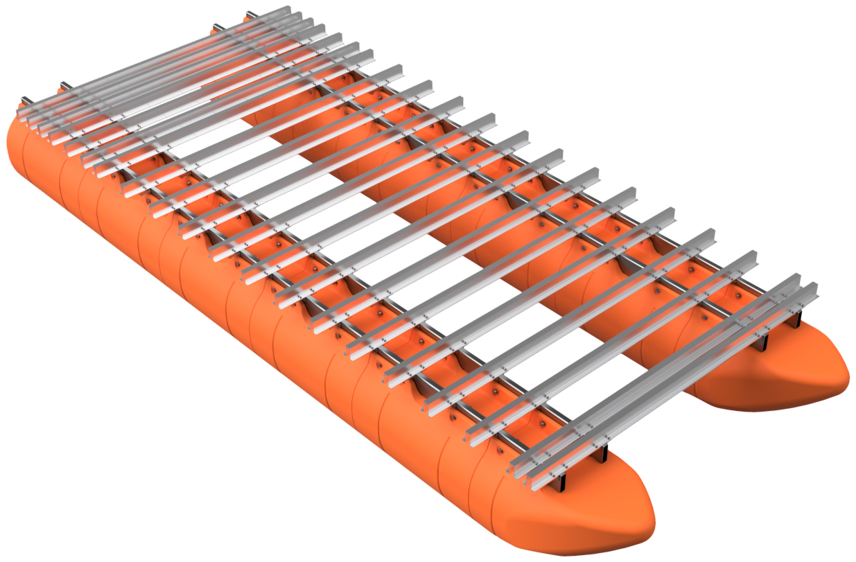
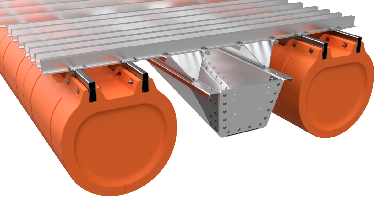
As described on the BigAssPontoonBoats.com main page, our large barge hybrid frame system is a concept that allows you to build a high-quality pontoon platform with the smallest investment possible. With this system, Tiny Pontoon Boats only provides the floats, crossmembers, transom (if you choose to purchase our transom), and a bracket alignment jig plate for physical parts. You are responsible for obtaining the required 6"x2" stainless steel tubes for the pontoon assemblies, weld-on crossmember brackets, 2-4 pieces of stainless flat bar, and assembly hardware (assembly/installation hardware for transoms are included when purchasing our transom systems). This arrangement allows you to build a high-quality large pontoon barge system and keep your costs as low as possible (parts and shipping).
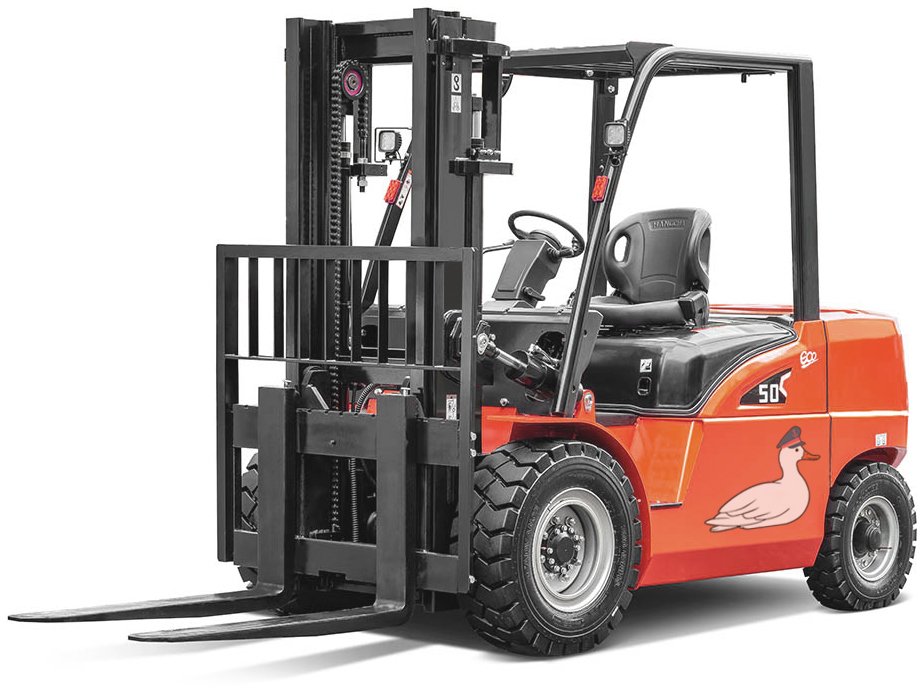
After you purchase your kit, you will be provided with a shopping list that includes required frame tube lengths, weld-on bracket quantities, and a full list of required hardware. We will line up an order for the weld-on brackets through SendCutSend.com (you order directly through them), provide a list of required hardware to purchase from McMaster-Carr, and if requested, we will contact local steel suppliers for quotes on the rectangular frame tubes. We will also provide you with a diagram showing the recommended crossmember/weld-on bracket placement for your barge. The Tiny Pontoon Boats (BigAssPontoonBoats.com) hybrid-framed large barge system is an industrial-sized pontoon barge system that requires welding equipment and experience, lifting equipment, a large work space, as well as larger basic tools to build. If you are not an experienced welder or do not have the equipment we specify, we strongly suggest contacting a local welding and fabrication shop to complete your assembly. This is NOT an "anyone can do it" system, so don't fool yourself if you don't have the proper equipment or skills to carryout one of these builds. Also, the components of these systems are large and heavy, especially as your assembly moves forward. Moving parts and assemblies for this system will require lifting equipment (forklift, loader, or over-head hoist system). Unlike our smaller bolt-together boat systems, our hybrid-frame large barge systems don't allow for error in assembly and failure to follow our instructions can cause expensive, or at least time consuming errors. Take your time, work as a team (not a single-person project), and follow our instructions closely. If questions occur, CALL US. |

|
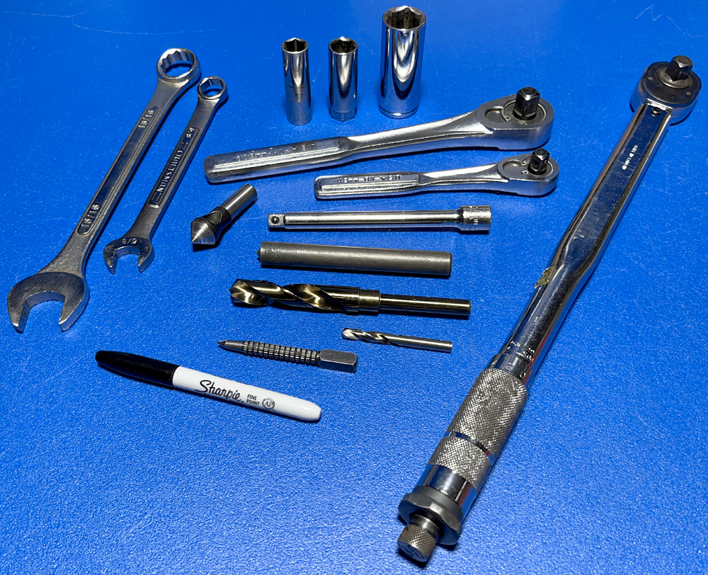
REQUIRED TOOLS & MATERIALS
Construction of your hybrid-framed barge sytem requires both advanced and basic tools. These kits require welding and lifting equipment, as well as simple fabrication tools and wrenches. Below we have provided a list of the tools required for construction for this type of barge sytem.
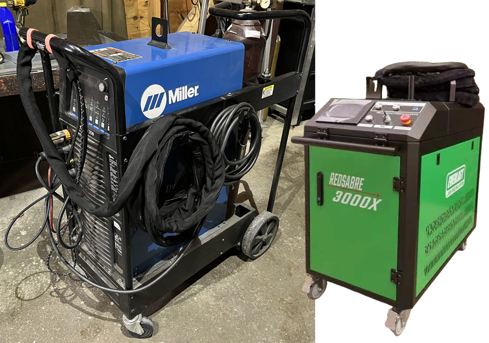
PRO TIP: This system requires welding of 3/16" thick stainless crossmember mounting brackets to a stainless tube that fits into your pontoon floats. We strongly recommend TIG or laser welding these brackets in place. MIG or stick welding is far more likely to cause distortion of the 6"x2" tube the brackets get attached to and we strongly recommend against using MIG or stick welding methods when building this system. If you are building multiple barges, or setting up a new production line for assembly of our hybrid frame systems, we recommend a wire-feed laser welder like the EverLast Redsabre machines. These machines require little training and provide high-quality results with very little distortion. If you're shopping for this sort of equipment, please do us a favor and click on our affiliate link below. In our example pictures, our welds will be completed with a Miller Dynasty TIG welder by our in-house master welder (25+ years of experience). Below we have provided two lists. One list is the required tools and the other is for the materials, parts, and hardware required for this system that are NOT provided by Tiny Pontoon Boats. Once again, we will provide you with the quantities required for anything you need to obtain after your order is placed, or prior per request. REQUIRED TOOLS
REQUIRED MATERIALS & HARDWARE
(NOT INCLUDED - REQUIRED QUANTIES VARY)
|
|
|
STEP 1
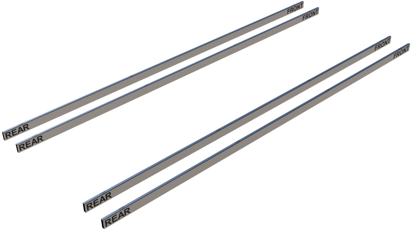
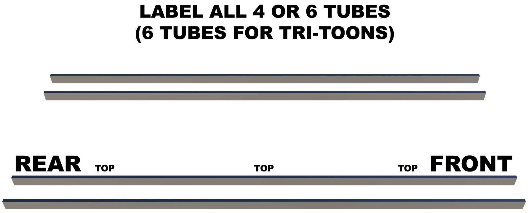
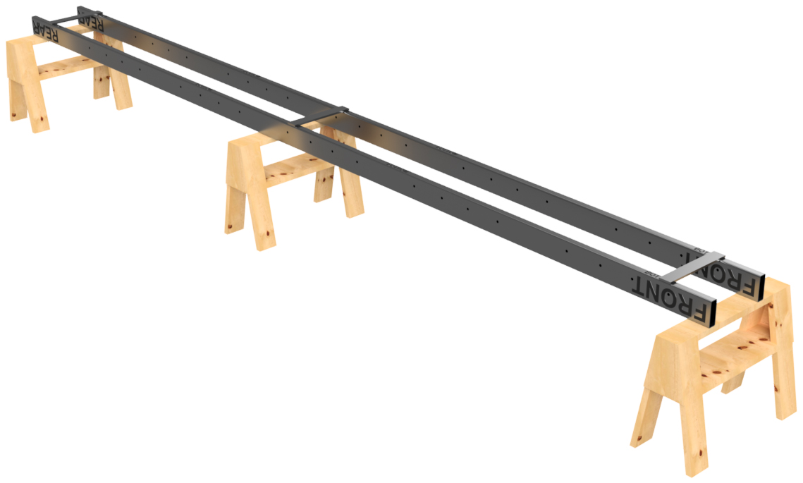
Each large barge system requires 2 lengths of 6"x2", 3/16" wall rectangular stainless steel tube per each row of floats. 1/8" wall tube is acceptable only for very specific applications. When you order your barge system, we will inform you exactly what lengths are required for your specific build. If building a barge with 3 rows of floats WITH a transom, the central pair of tubes will be shorter to allow space for your transom. When your frame tubes are cut to length, they MUST be cut accurately or your barge will be more difficult to build. We make note of how to compensate for inaccurately cut tubes in step 20.
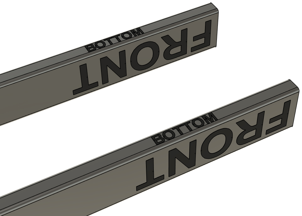
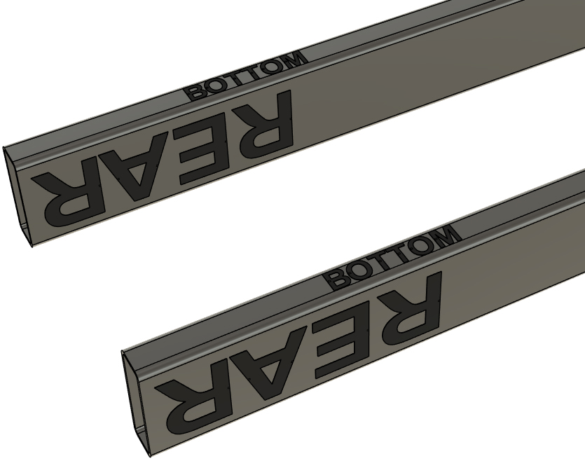
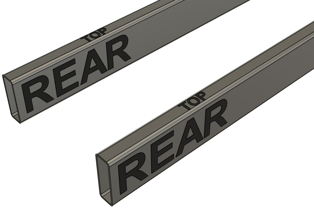
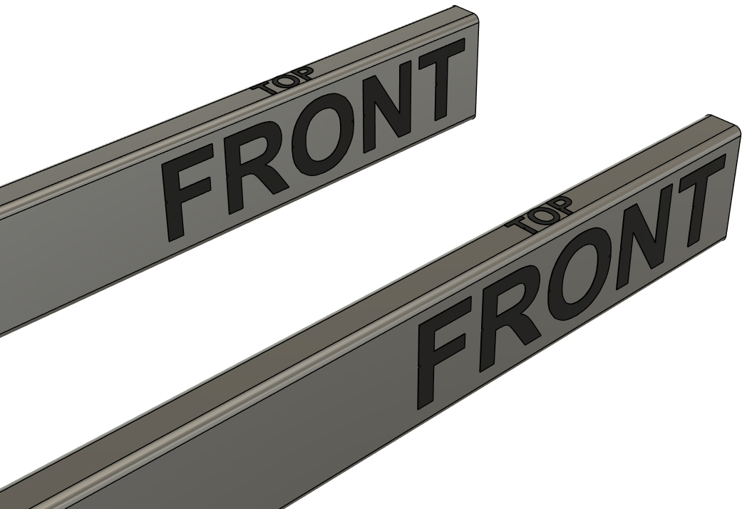
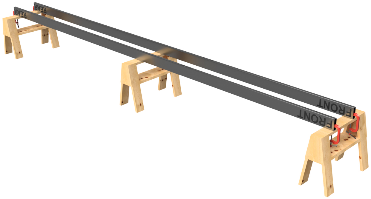
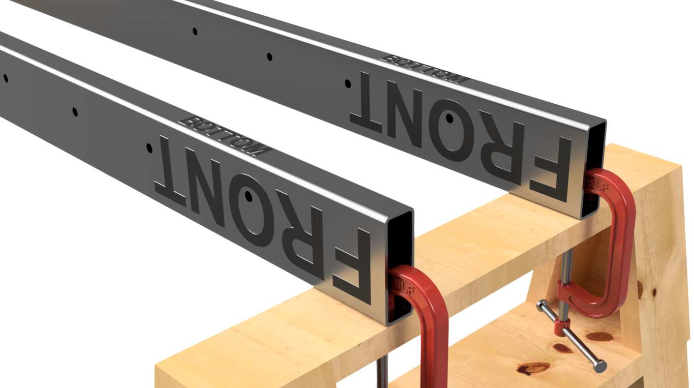
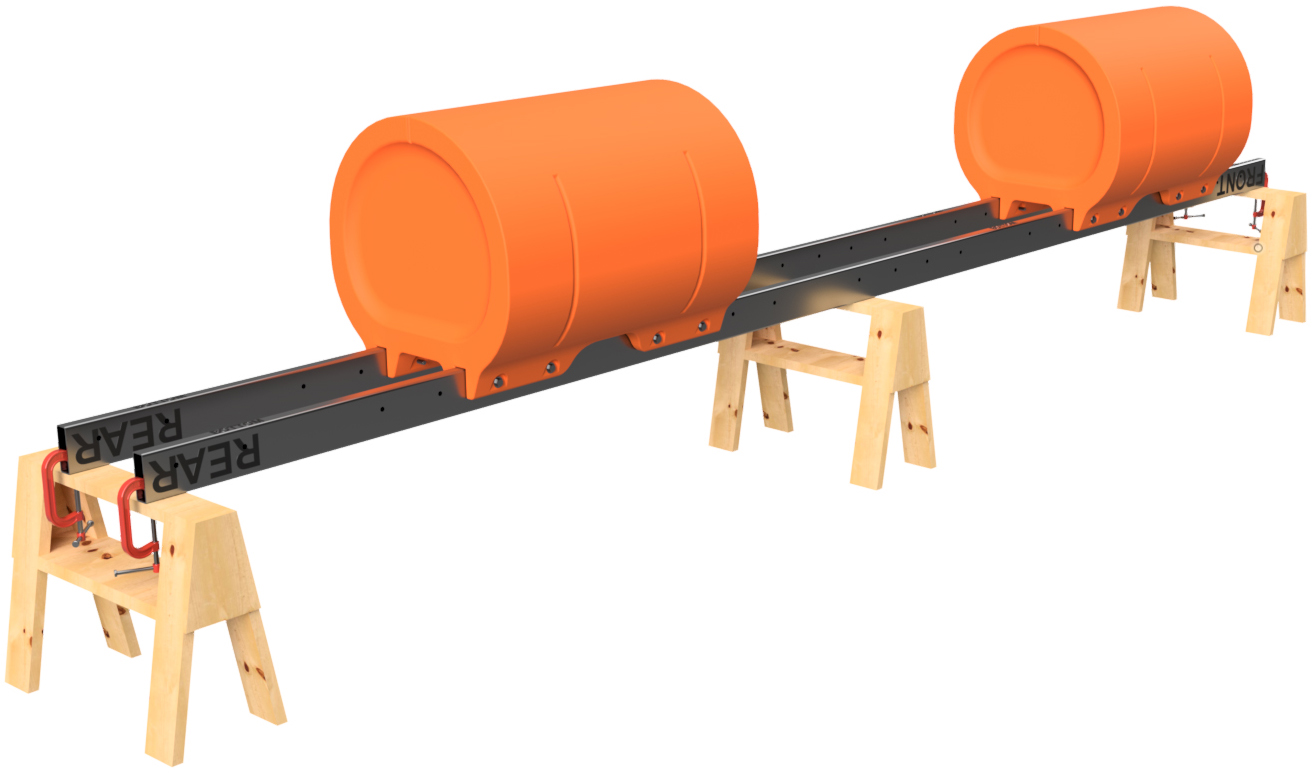
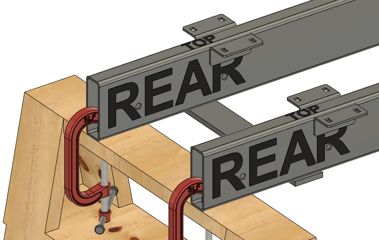
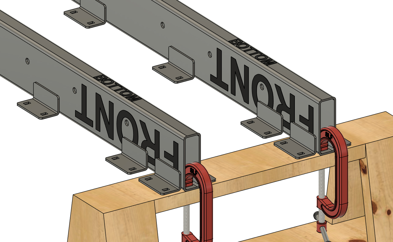
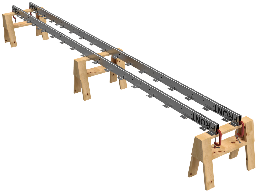
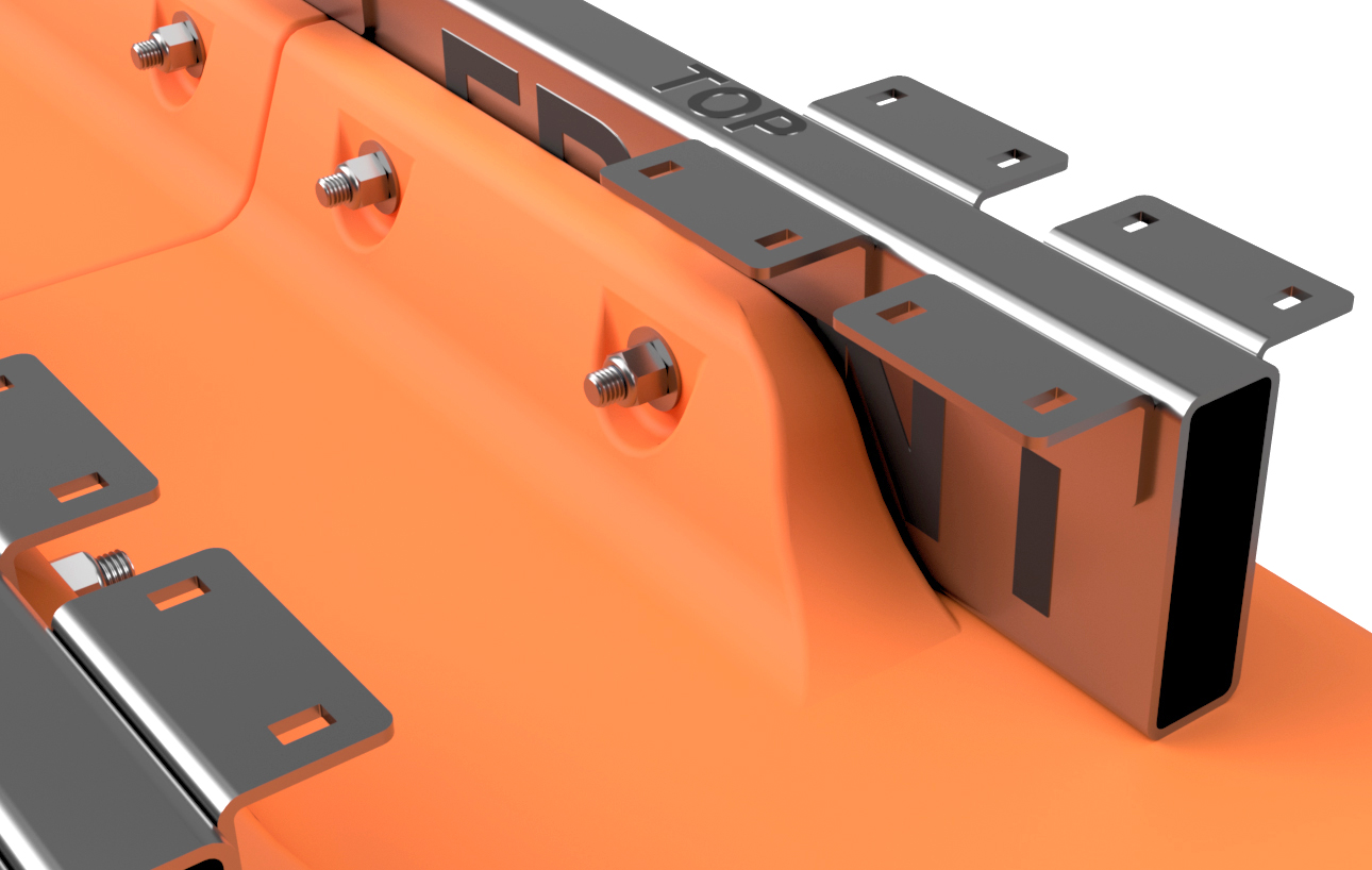
Start by laying out your frame tubes, remove any burrs on the cut ends, and clearly label the FRONT, REAR, TOP, and BOTTOM of the tubes as shown. We like using a paint marker for this, but what is most important is VERY clearly marking the tubes as shown. We recommend writing REAR on both of the broad sides of one end of the tube and the same goes for the front. We also recommend writing TOP and BOTTOM several times on the tops and bottoms of the frame tubes. These tubes are going to be moved around a fair amount from this point forward, so you want to make certain that the orientation of ANY of these tubes is not mixed up.
|
|
|
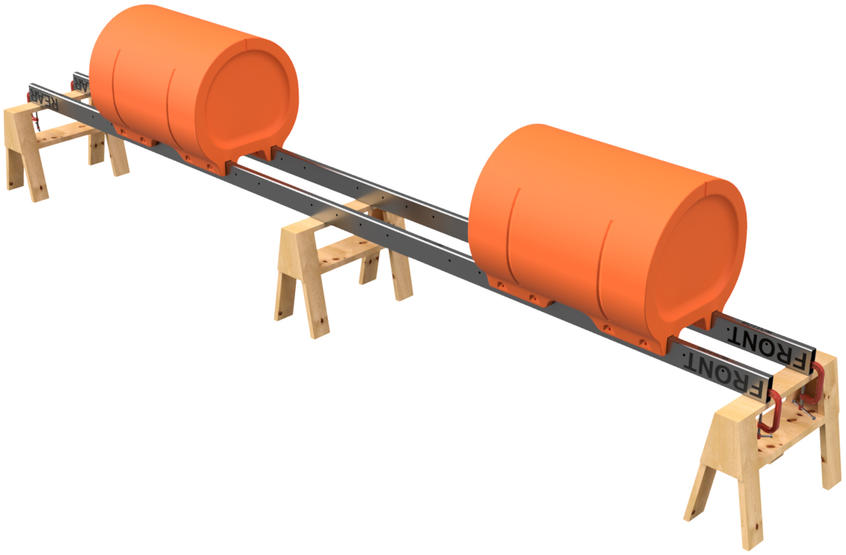
STEP 2
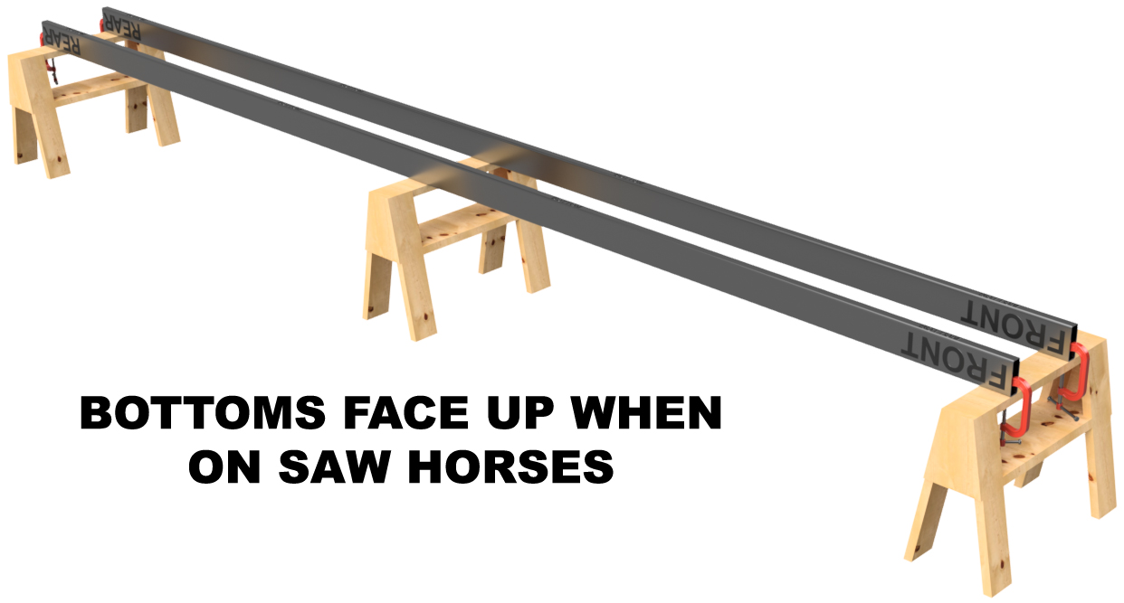
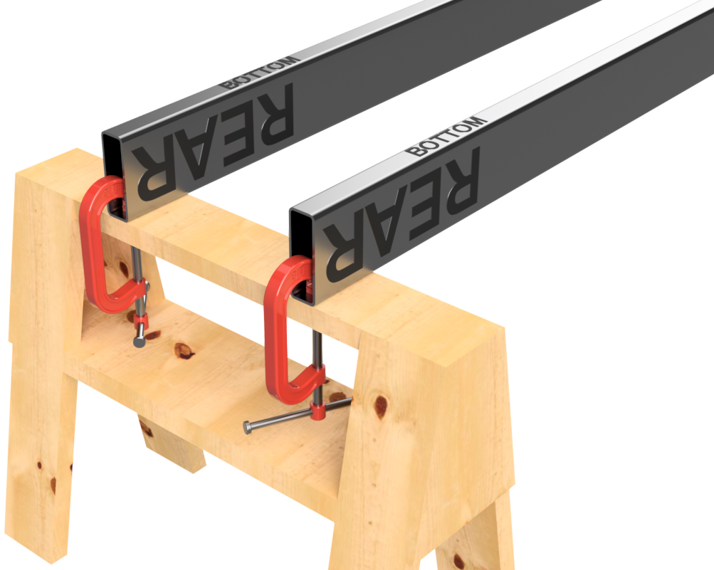
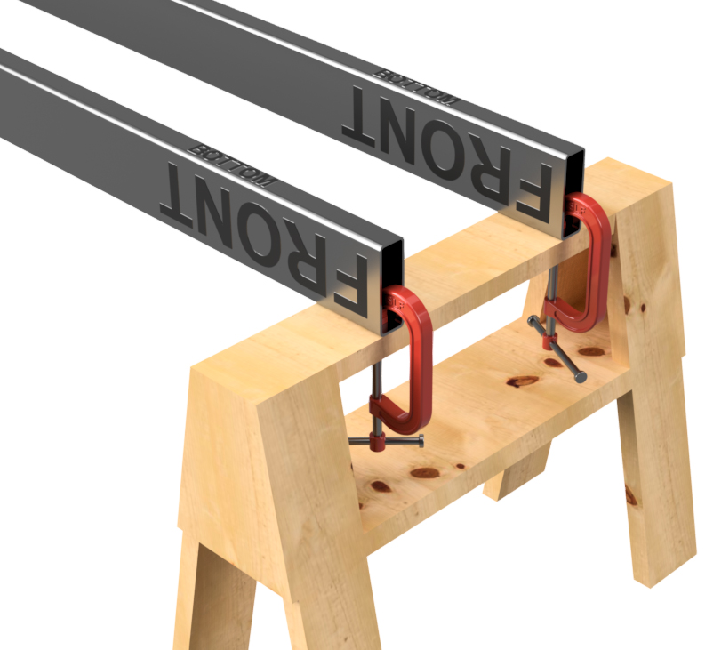
Place two of your 6"x2" stainless tubes (of the same length) across 2, 3, or 4 saw horses as shown. In portion of the instructions, the example we are working through is 10'x24' barge with 2 rows of floats. For this application, we require 3 saw horses. Place the two tubes so that the BOTTOMS are facing upward and that the FRONT and REAR labels are on the same sawhorses as shown. Measure and place the two tubes so that there is 14" between the two tubes (16" on-center). Use a square to ensure that the REAR ends of the tubes are even as shown below. Adjust placemen as necessary. Loosely clamp the two tubes to the top of your outer sawhorses as shown.
|
|


|
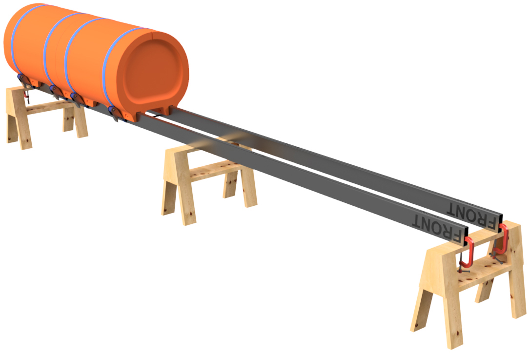
STEP 3
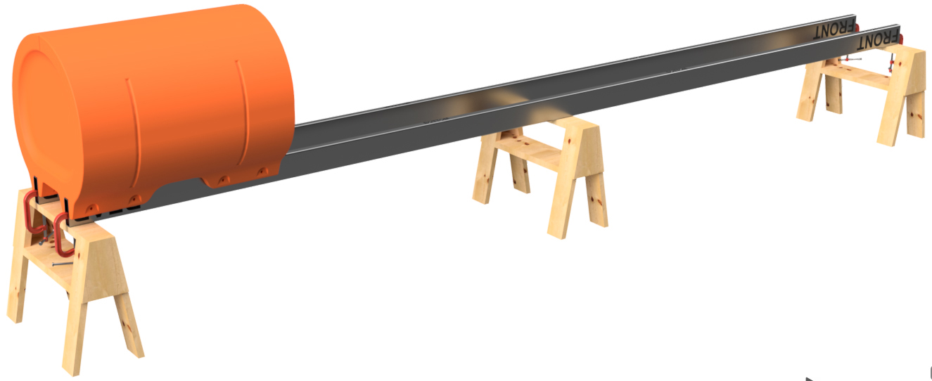
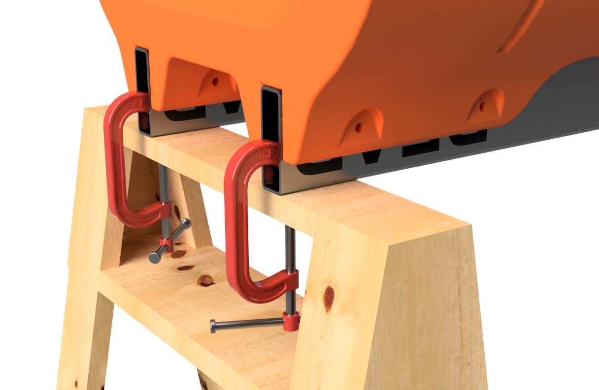
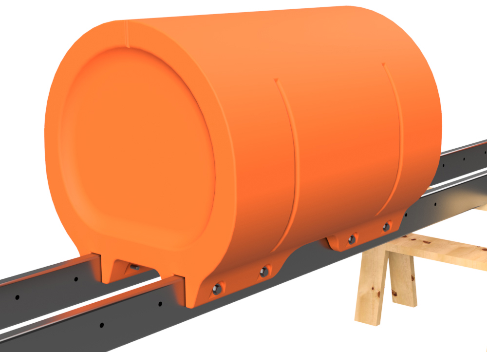
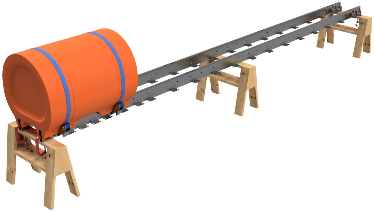
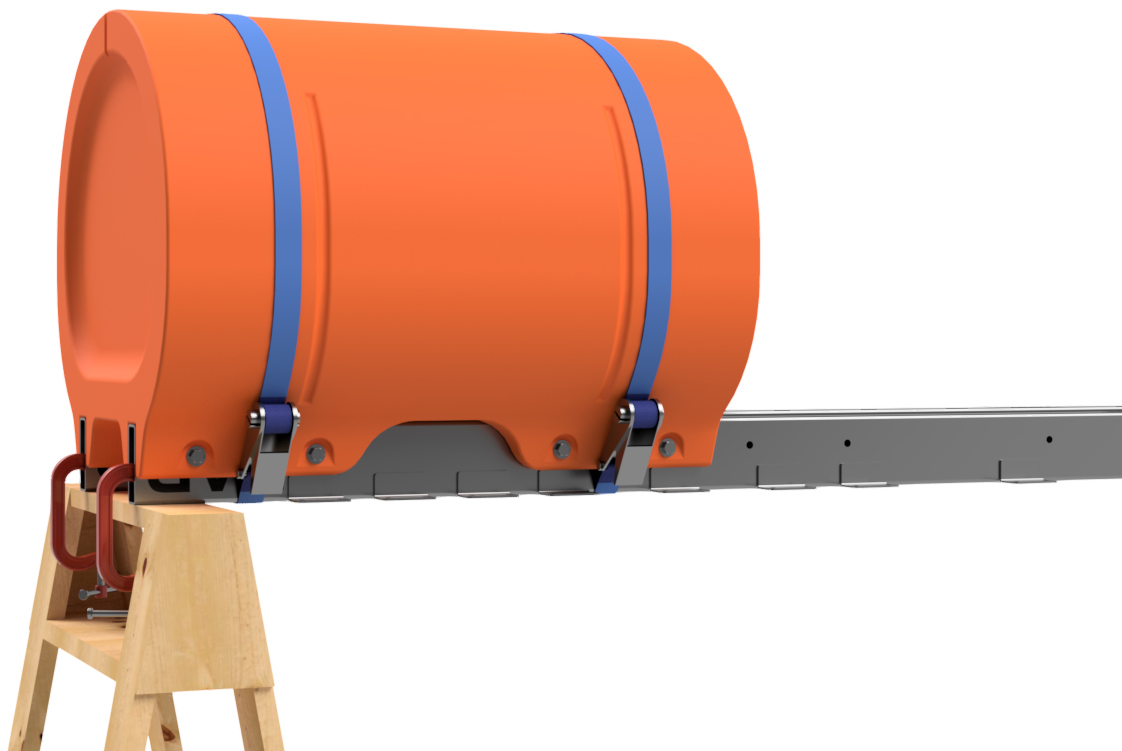
Place one of your straight floats (blunt-end floats) on the ENDS of the pair of frame tubes that are across your sawhorses. You may have to loosen the clamps on one of the 6"x2" tubes. Adjust the placement of the float so that the end is even with the ends of the tubes. Use your square to ensure that the REAR ends of the tubes are still even. Fully tighten the clamps that are holding the frame tubes to the saw horses.
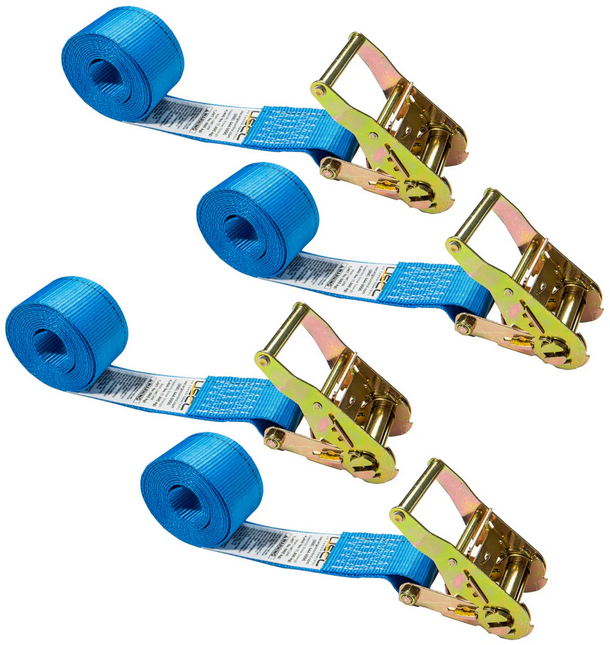
Use two ratchet straps to ensure that the float is seated onto the frame tubes. Make sure the ratchet straps are TIGHT as they will be holding the position of the float as we place other floats against it moving forward. When we build these barges, we prefer the 2" wide "endless" ratchet straps from US Cargo Control. We use their 15' long straps for this. You will require straps no shorter than 12' ratchet straps for this operation.
|
|
|
STEP 4
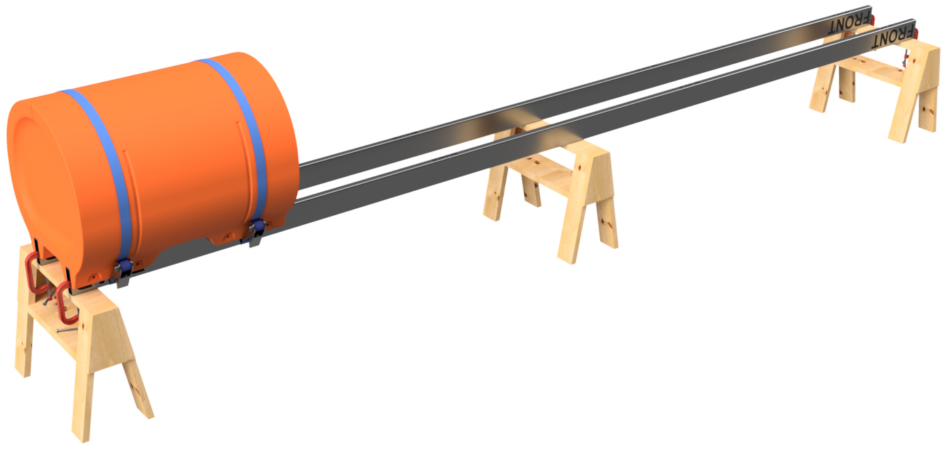
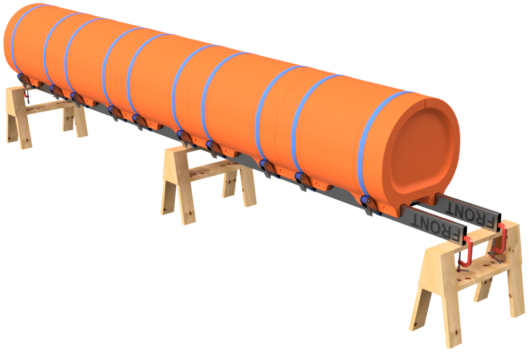
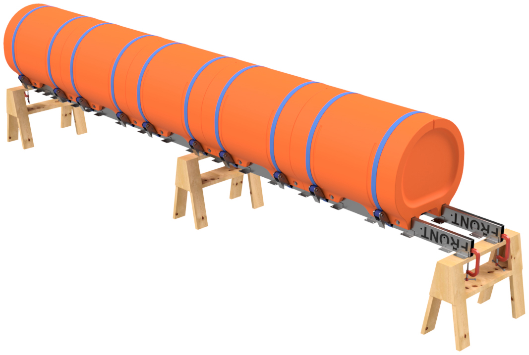
Place the next straight float section onto your frame tubes. Butt it against the float you just installed. You can use a rubber or plastic mallet to tap it against the other float. Double check that the first float is still even with the ends of the frame tubes and then install two ratchet straps around the newly installed straight float. Be sure that the straps are tight so the float section is securely seated against the frame tubes.
Repeat this process until all the straight floats for the pontoon assembly are installed onto the pair or frame tubes. As you do this, be sure to keep an eye on the end of the pontoon assembly to ensure that the last float in the assembly is still even with the end of the frame tubes. Make adjustments as necessary. |
|
|
STEP 5
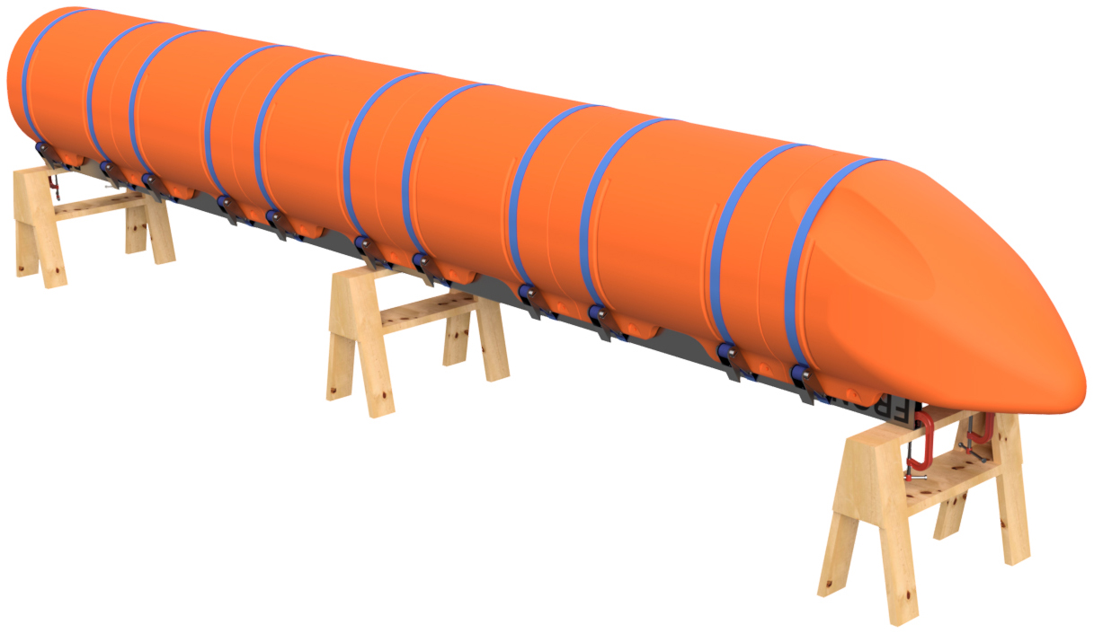
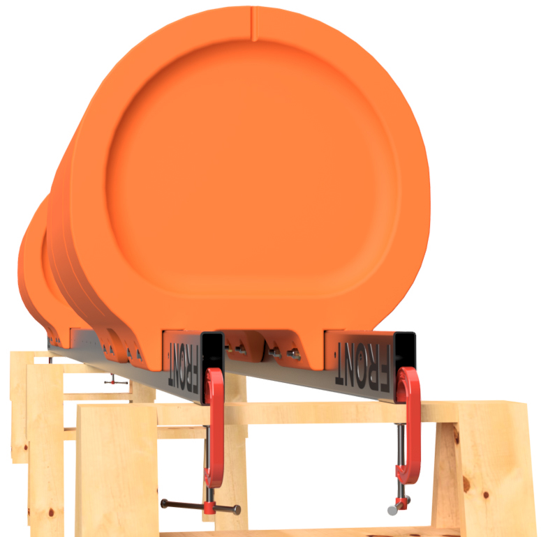
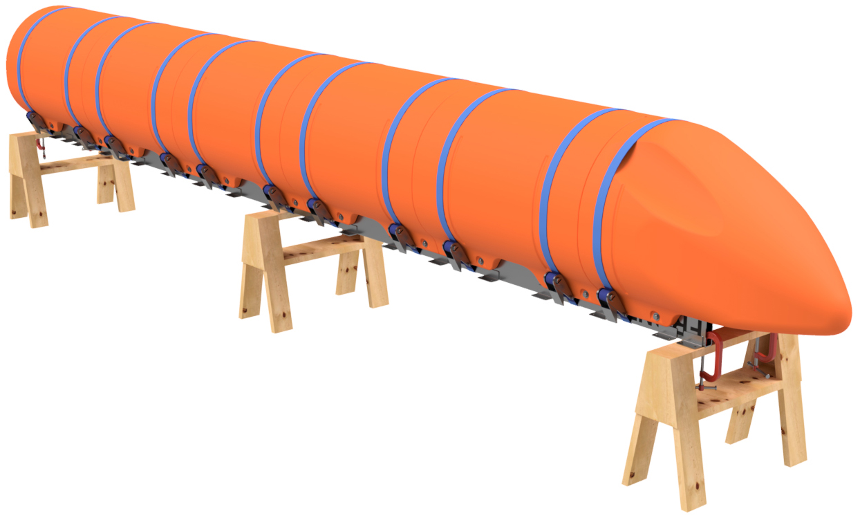
Place a nose cone float on the front of the pontoon assembly and push it against the last straight float. Install a ratchet strap around the portion of the float just before the taper. Due to the shape of this part, you will only be able to install one ratchet strap.
|
|
|
STEP 6
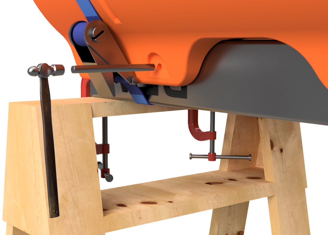
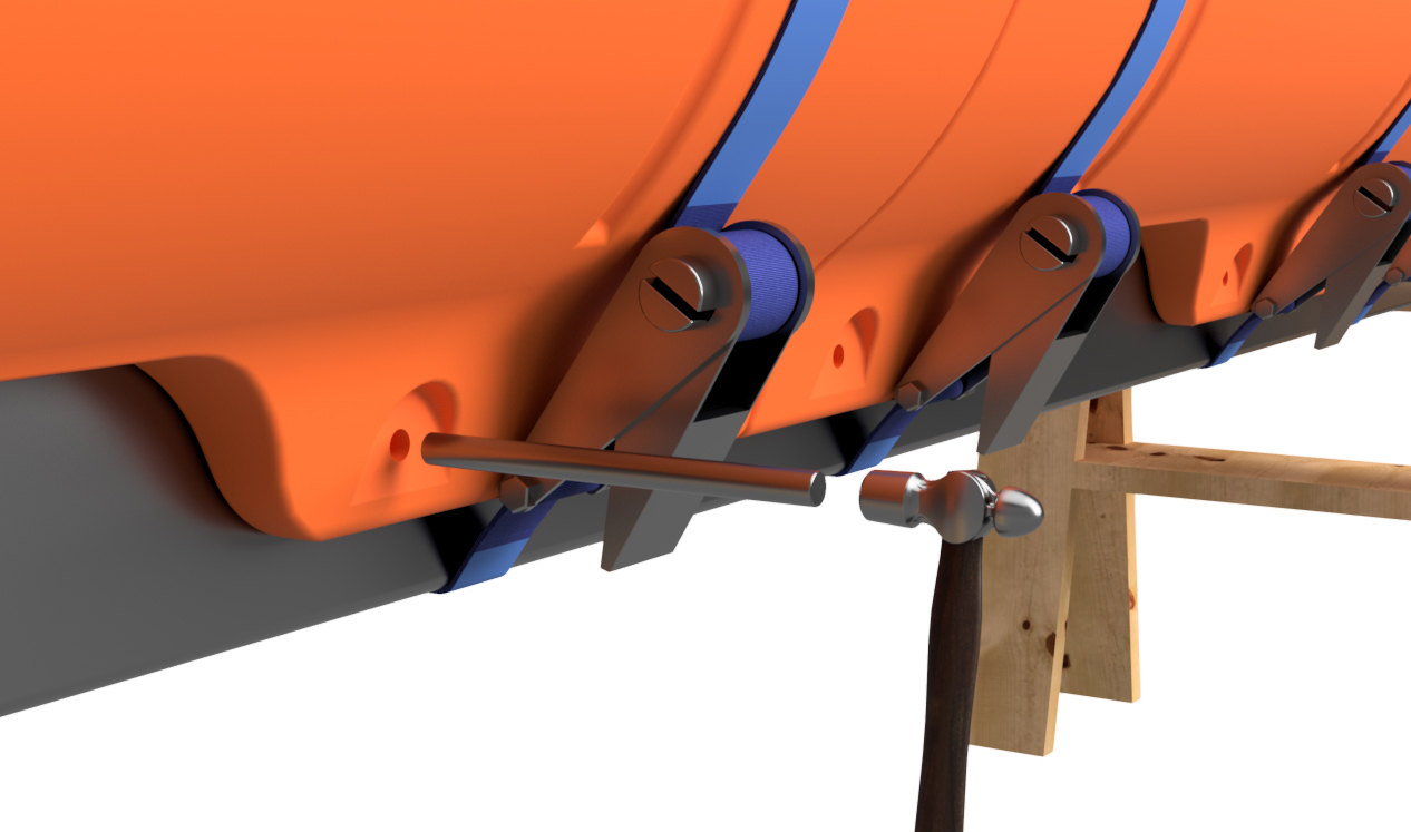
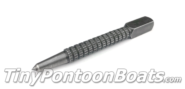
Using a 5/8" transfer punch, go down both sides of both sets of mounting channels on the plastic floats and use the punch with a hammer to mark EVERY bolt hole position through the molded-in bolt holes in the floats. This will require a solid hit on the transfer punch to make the mark. You will have to do this from both the outside set of holes and the inside set of holes. This means that you'll have to go under the pontoon assembly on your saw horses to mark the inner holes. It's inconvenient, but 100% necessary.
|
|
|
STEP 7
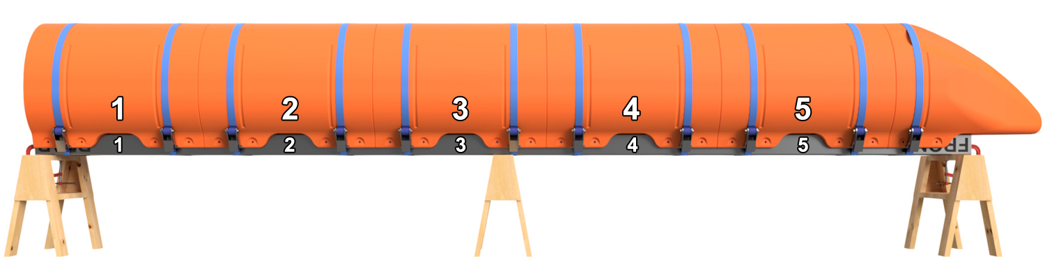
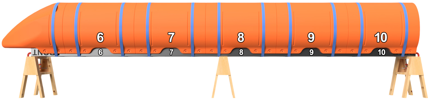
Using a marker (ink or paint), number the positions of the straight floats on the frame tubes as shown. Do this on both sides of the pontoon assembly. For instance, if you're building a 20' long pontoon, you'll want to label position 1, 2, 3, 4, and 5 on one side and 6, 7, 8, 9, and 10 on the other. This ensures that you don't mix up the positions of the floats after you drill holes. You can number the nose cone poisition if you'd like, but it will only fit in one position anyhow. We chose not to number the nose cone in our example pictures. You can use a piece of masking tape to write on or you can use a marker to write on the floats and frame tubes. If using a marker, lacquer paint thinner will remove the ink or paint after assembly, and the paint thinner will not hurt the plastic or the stainless steel.
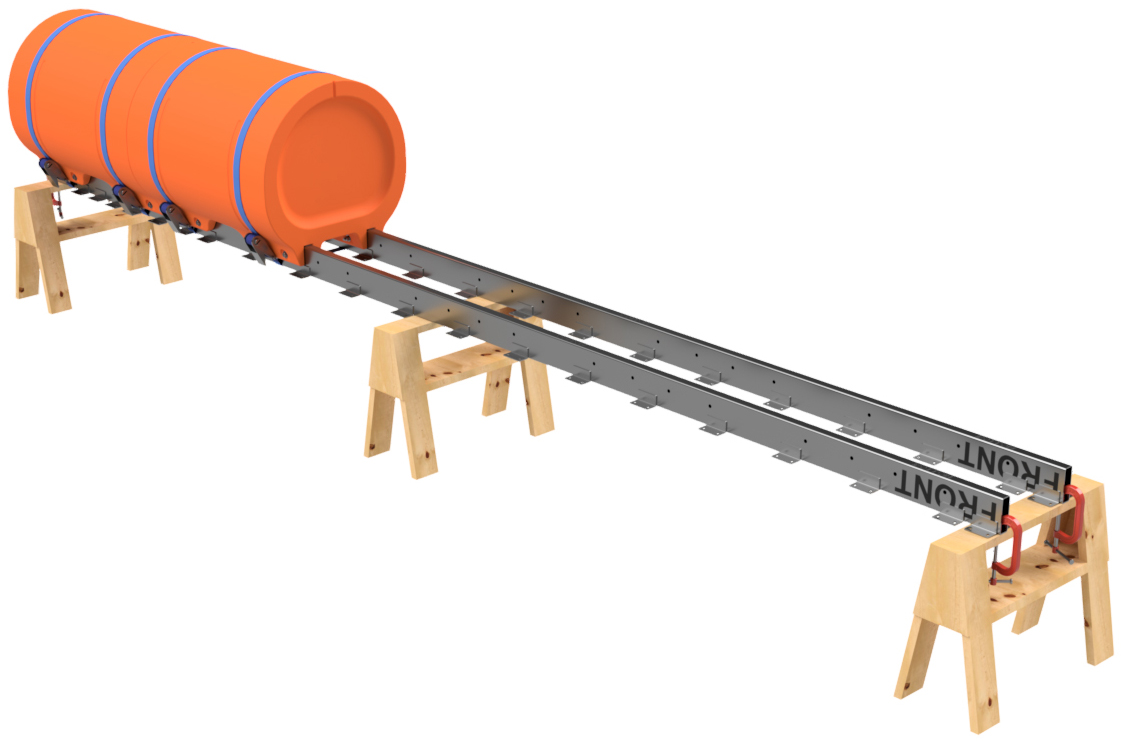
Remove the ratchet straps and pull all the floats from the two frame tubes. |
|
STEP 8
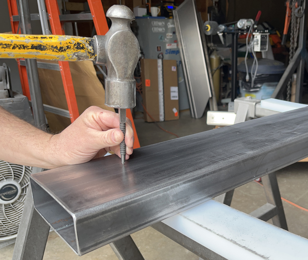
Using a standard center punch, make the marks you made on the frame tubes with the transfer punch in step 5 more pronounce. This will make the holes easier to drill in the next step.
 |
|
|
STEP 9
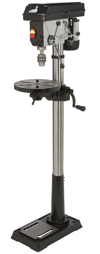
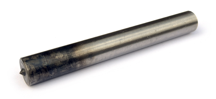
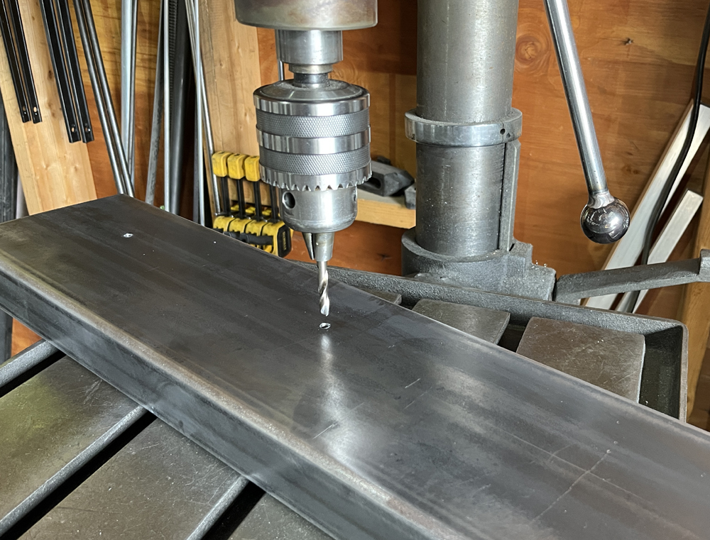
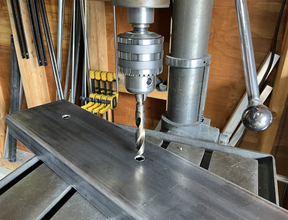
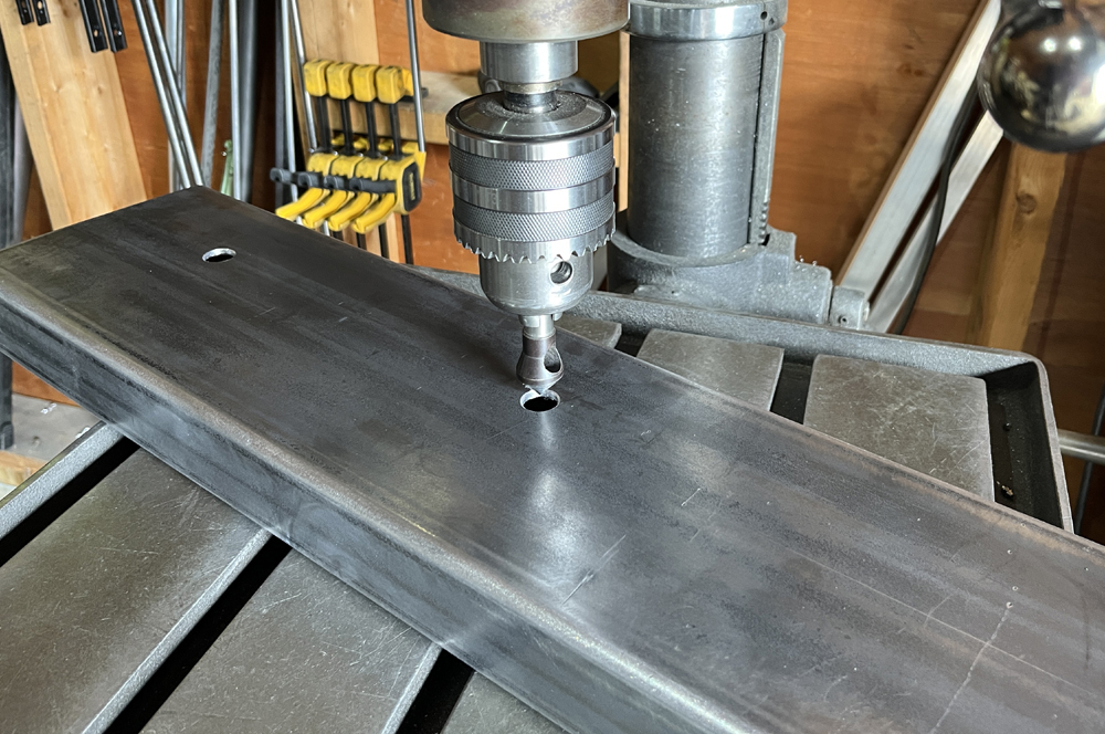
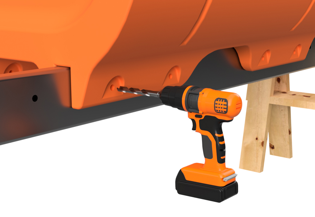
IMPORTANT: Stainless steel work hardens quickly and requires use of cobalt alloy drill bits. Standard high-speed steel drill bits will be destroyed quickly if used for this project. We repeat, this project requires COBALT ALLOY DRILL BITS and we strongly recommend using the bits listed in the "REQUIRED TOOLS" table at the top of this page. Also, drilling into stainless steel requires an aggressive chip load. This means you should keep the RPM low on your drill and put a fair amount of pessure on the bit. Any experienced fabricator will understand this information.
Using a SHARP (prohibits wandering of the bit) 1/4" diameter COBALT alloy drill bit, drill through ONE WALL of each 6"x2" frame tube at each marked position. DO NOT drill all the way through both sides of the tubes during this operation. Drill through every marked position on one side of each part, flip it, and drill through every marked position on the other side. After drilling all the 1/4" holes in both frame tubes, use a 5/8" diameter drill bit to drill through every 1/4" hole. Once again, only drill through one wall at a time for each hole position. For this operation, drilling the holes with a hand drill will be quite tough and we strongly recommend use of a drill press. Also, this is at least a 2-person operation and requires use of stands on either side of your drill press. Frame tubes are heavy, especially for long boats, so be careful and take your time. After drilling the holes, they must be deburred. We recommend using a "zero flute" countersink type drill bit for this operation. Once again, we recommend using the bit we list in our "REQUIRED TOOLS" as we find it works best for this application. |
|
|
STEP 10
With all your holes drilled in your frame tubes, place them back on your saw horses in the same position as before. Aim the "FRONT" and "REAR" ends of the tubes in the same directions and place the "BOTTOM" facing upward as shown. Space the tubes about about 14" apart as you did in Step 2. Loosely clamp the ends of the tubes to the saw horses.
Place 2 or 3 straight floats in their numbered positions that are one float in from the ends as shown. If you are building a boat 30' or shorter, 2 floats will do the trick as shown in our pictures here. If you are building a boat longer than that, install a float in a central position as well. The floats are just to hold the center-to-center spacing for step 12. Align the holes in the floats with the holes in the frame tubes. You may have to reinstall the ratchet straps to align the holes. For clarity, we have not shown the straps in our example pictures for this and the next step.
|
|
|
STEP 11
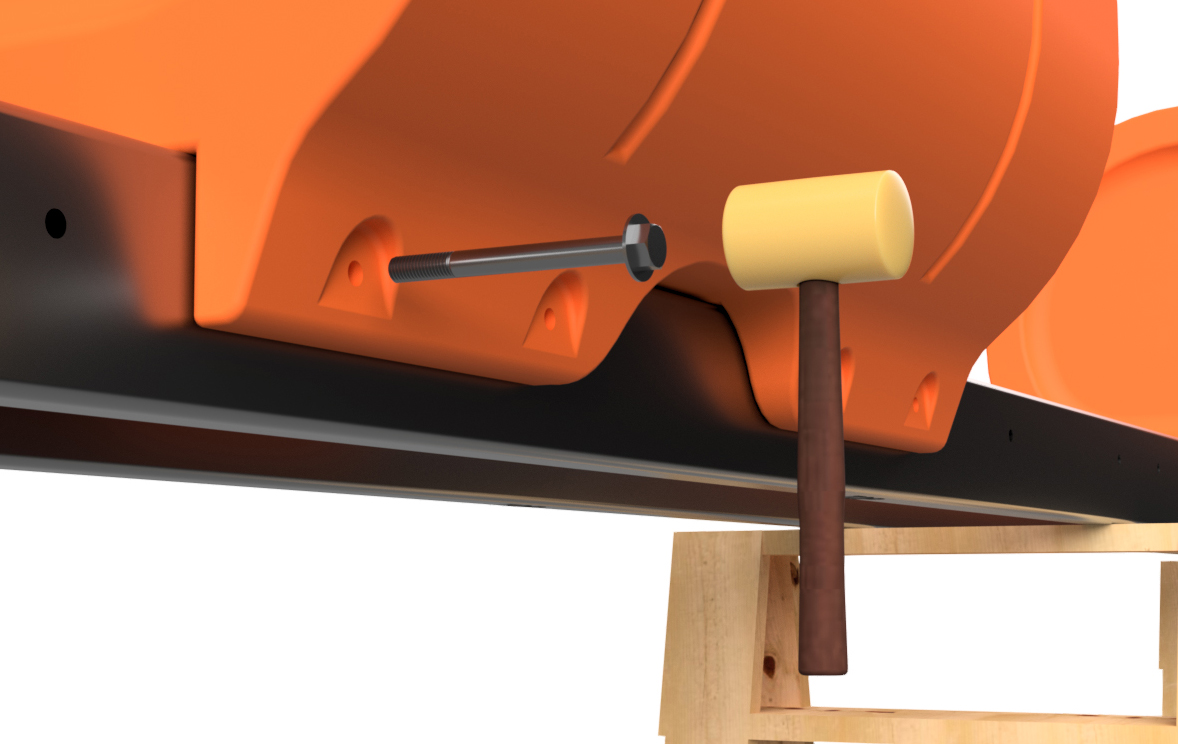
With a 5/8" drill bit mounted in your hand-held drill, start at one end of the rearmost float on your frame tubes and drill through one of the the rearmost bolt holes. Drill all the way through both sides of the frame tube on that side of the float. You will be drilling inward from the side of the float. When doing this, go slowly, as your drill bit should only be clearing chips and verifying hole alignment, not drilling a new hole.
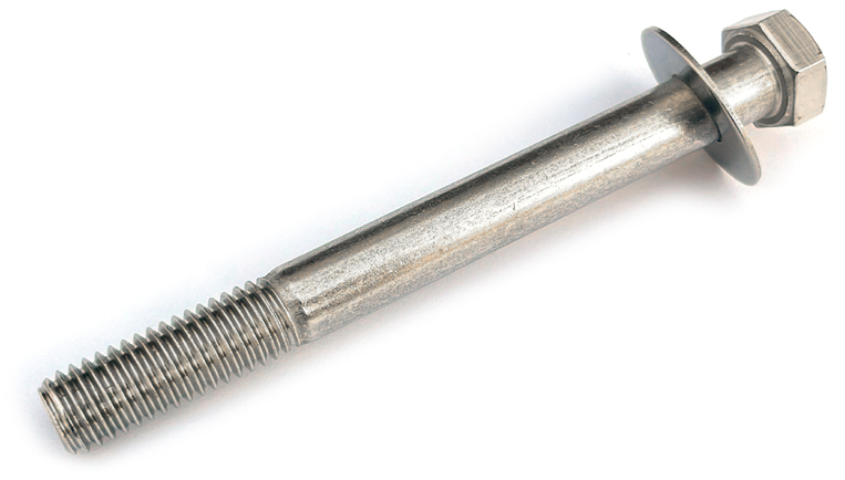
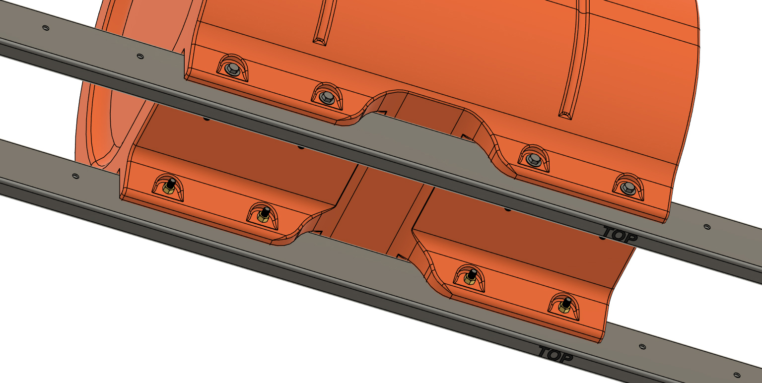
Insert one of the 5/8" x "6 1/2 hex bolts with a 5/8" flat washer from the outside position, and tap it through the hole with a hammer. We prefer to use a plastic hammer for this. Drill through the next float bolt hole and insert a bolt with washer. Do this on both sides of the float until each bolt hole has bolts installed. DO NOT INSTALL NUTS YET. Repeat this for the other float/floats placed onto your frame tubes. DO NOT INSTALL NUTS YET.
|
|
|
STEP 12
Use a rag to clean any chips off of the bolts that have been driven through the bolt holes and loosely install STANDARD 5/8" STEEL nuts (NOT LOCK NUTS; DO NOT USE STAINLESS NUTS FOR THIS STEP OR THEY COULD JAM) onto the bolts as shown. These nuts are temporary.
|
|
|
STEP 13
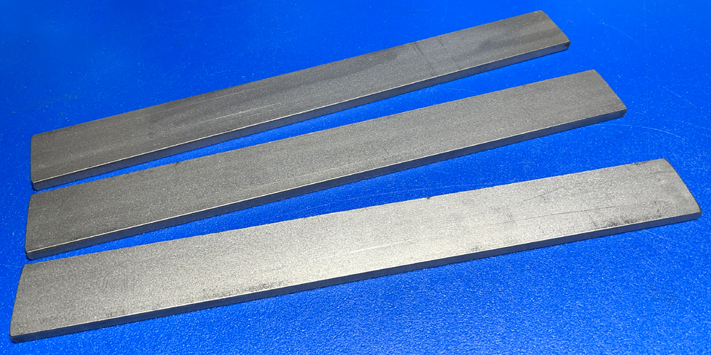
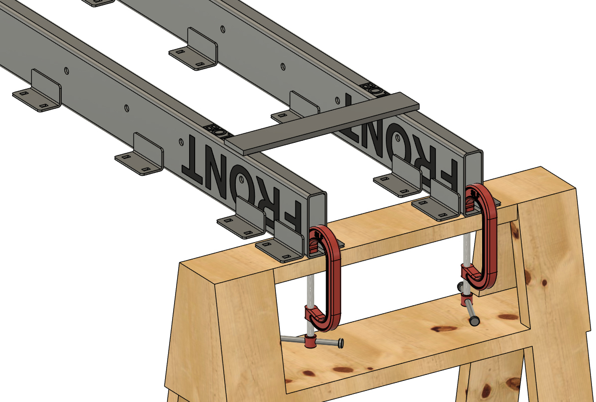
This step requires a quantity of 2-4 pieces of a 3/8" x 2" or 3" wide stainless steel flat bar cut to a 18" length. In our example pictures, we are using 3" wide bar. Be sure to use the same 304 grade stainless steel that you're using for your 6"x2" tube. If your boat is 30' or shorter, you need 3 lengths of this material. If you are building a longer boat, you will require 4 lengths. These bars are used to temporarily hold the spacing of your frame tubes for the steps that follow.
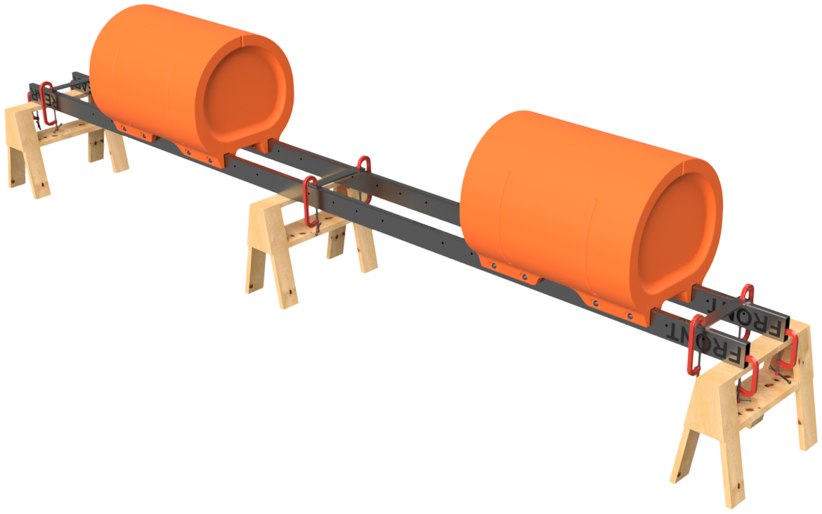
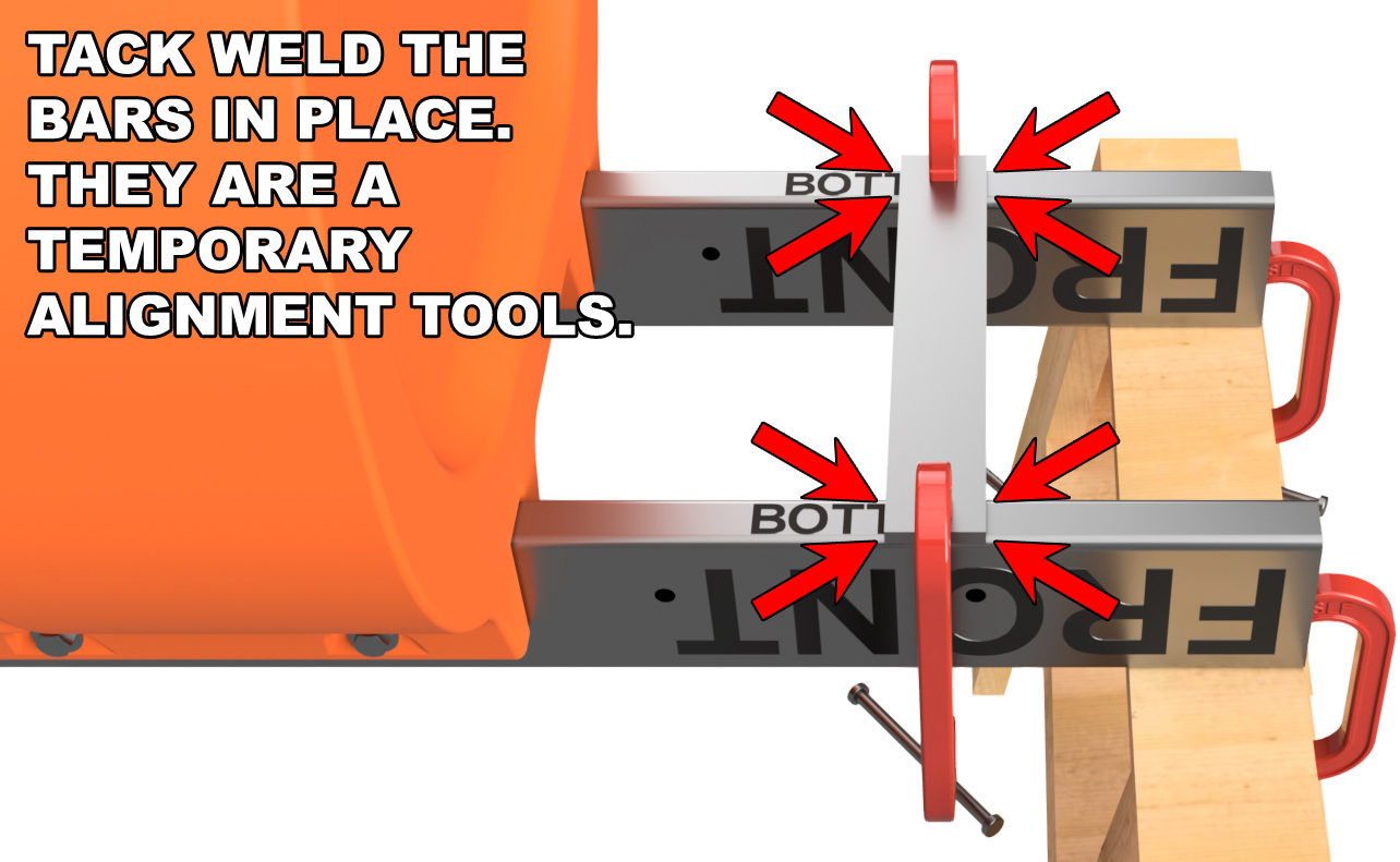
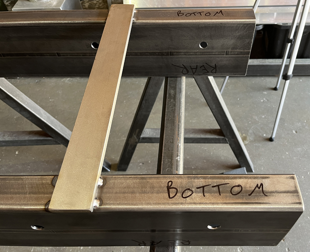
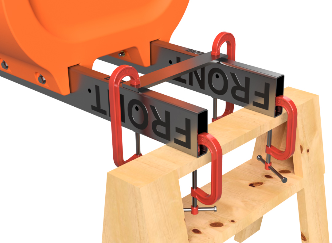
Clamp a flat bar across the "FRONT" and a bar across the "REAR" ends of the 6"x2" frame tubes. The bars will be on the upward facing "BOTTOM" side of the tubes. Now clamp one or two more pieces across the central portion of the tubes. If you are building a 30' or shorter boat, you'll be clamping on a single centered bar. If you are building a boat longer than 30', clamp two pieces centered between your temporarily mounted outer and central float. The accuracy of the placement of these bars is not critical. Tack weld the bars in place using 308L welding rod or wire as we show in the diagram to the lower right. Do not weld all the a across the bar as these are only temporary supports. All of the welding examples shown from this point forward will be TIG welds and we used 3/32" diameter filler rod for these welds. We recommend using 1/16" or 3/32" diameter 308L stainless filler rod if you will be using a TIG welder for the welding procedures on your barge system.
|
|
|
STEP 14
Remove the temporary nuts and bolts from all the floats installed on your frame tubes. Completely remove the floats.
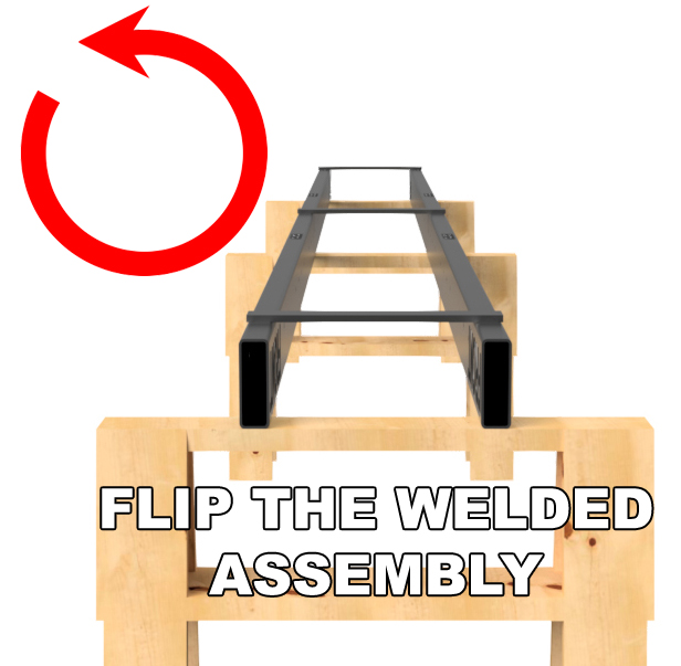
Remove all the clamps and carefully flip the frame tube assembly with the temporarily installed spacer bars. BE CAREFUL DOING THIS as the assembly is fragile and intentionally only tack-welded together. Also, this weldment will be very heavy, so this requires a team effort or lifting equipment to do safely. Clamp the frame tube weldment back to your saw horses. The "TOP" side of the frame tubes will be facing upward.
|
|
|
STEP 15
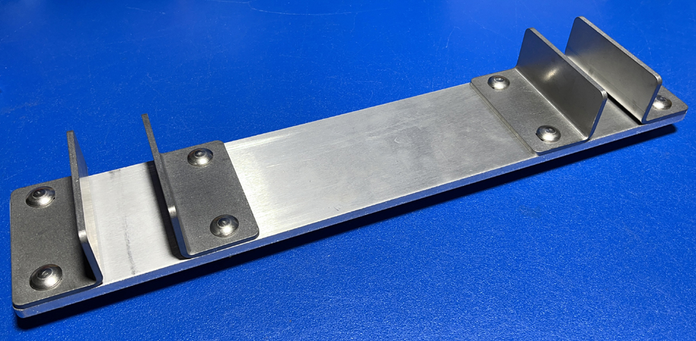
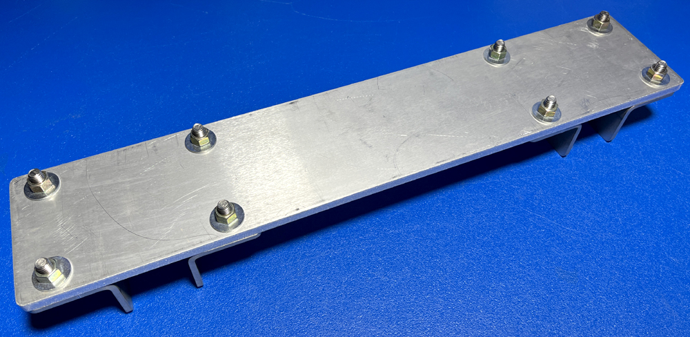
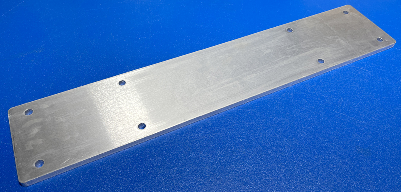
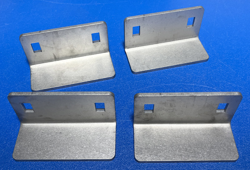
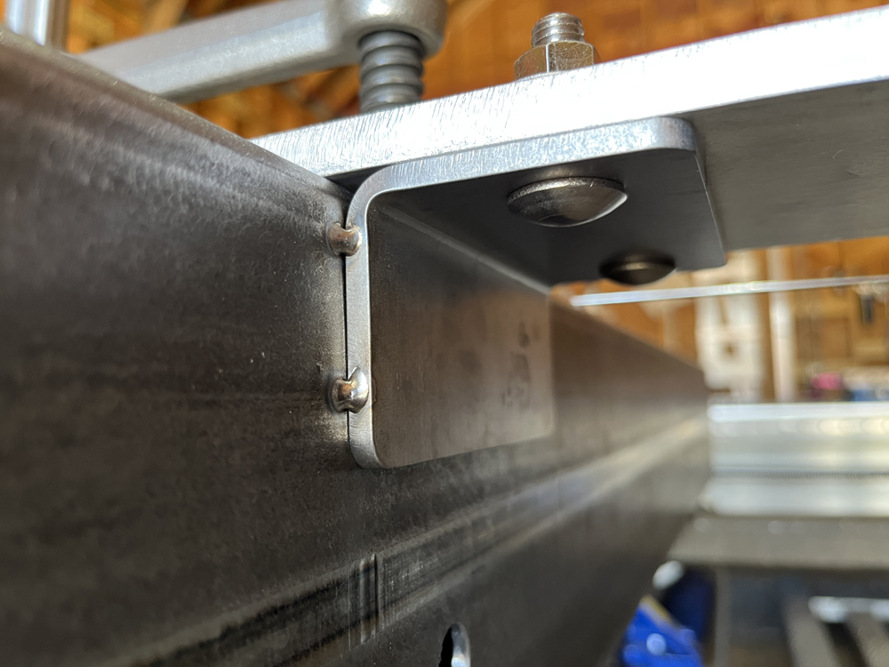
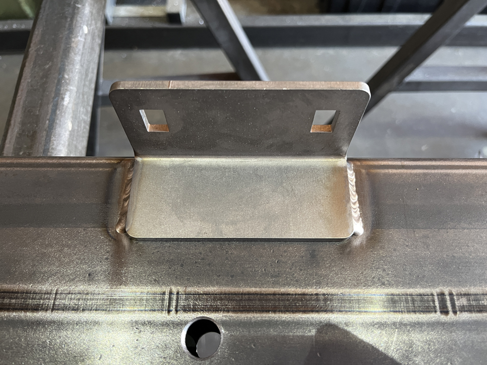
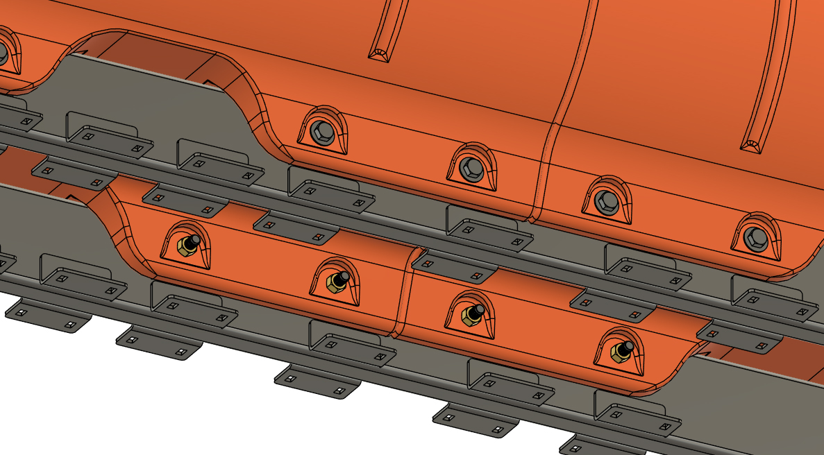
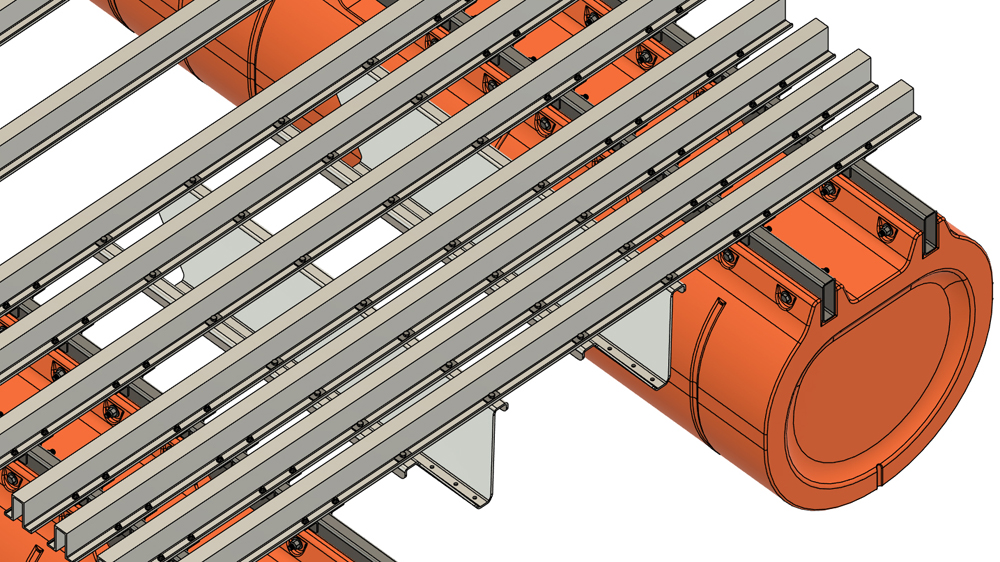
The Tiny Pontoon Boats hybrid frame system makes use of 3/16" thick laser cut and CNC bent brackets that you are responsible for ordering through SendCutSend.com (or similar supplier). These brackets need to be welded onto the side of the 6"x2" frame tubes that we've been working with in prior steps. When you order your kit, we provide you with a mounting jig that lines up these brackets for welding.
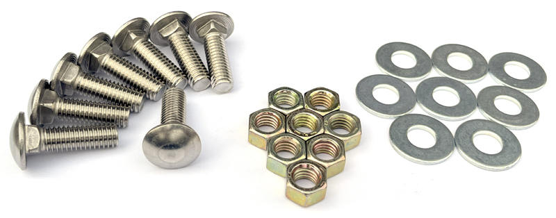
From the hardware that you sourced, select a quantity of 8 of the following: 3/8" x 1 1/4" stainless carriage bolts
Using the hardware listed above, loosely bolt 4 of the laser cut & CNC brackets to the plate as shown. We will be calling these brackets "crossmember brackets" from this point forward. The crossmember brackets have rectangular holes to accept the carriage bolts. Leave the nuts and bolts loose for the moment. As you will have to assemble this set of parts many times throughout the remainder of your project, we are going to refer to this assembly as the "crossmember bracket jig assebly" from this point forward.
|
|
|
NOTE
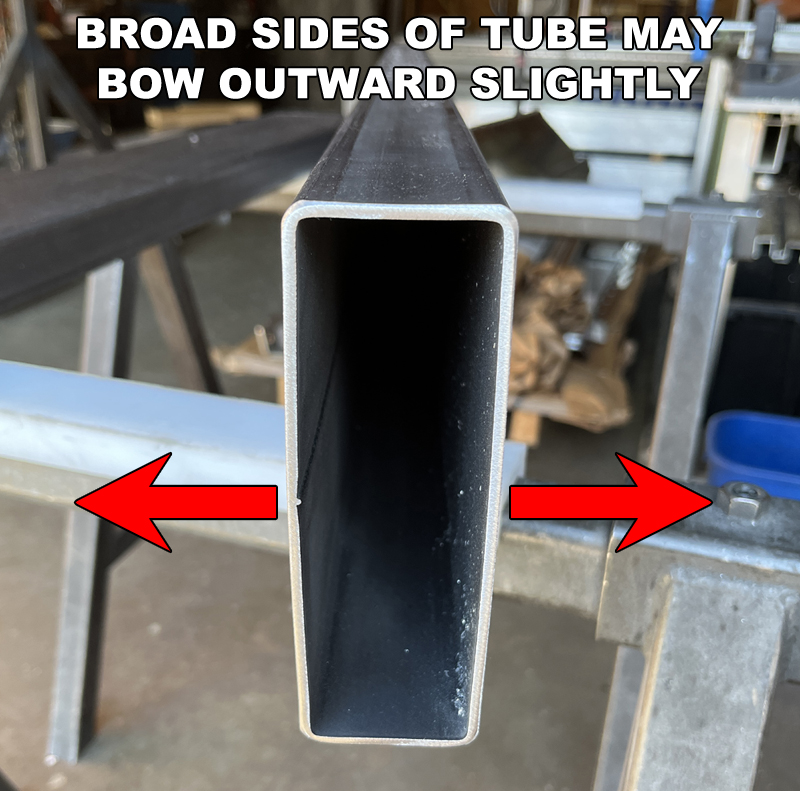
Stainless and mild steel tube is a formed product that rarely has perfect geometry. In this case, the 6"x2" tube we are using has a relatively thin and broad side wall (the 6" tall portion of the tube). Due to the geometry and the way this tube is manufactured, the broad sides of the tube often bow out a little from the center of the tube. This is 100% typical, but we still need to be aware of it. As you move foward, it is more important for the top of the crossmember brackets to stay parallel with the "TOP" of the frame tubes than for the vertical portion of the bracket to sit flat against the tube. Depending on the quality of the tube you sourced and the accuracy of the bend angle on the brackets, you may have to compensate a little with weld. Any seasoned welder or fabricator will be accustomed to this concept.
|
|
|
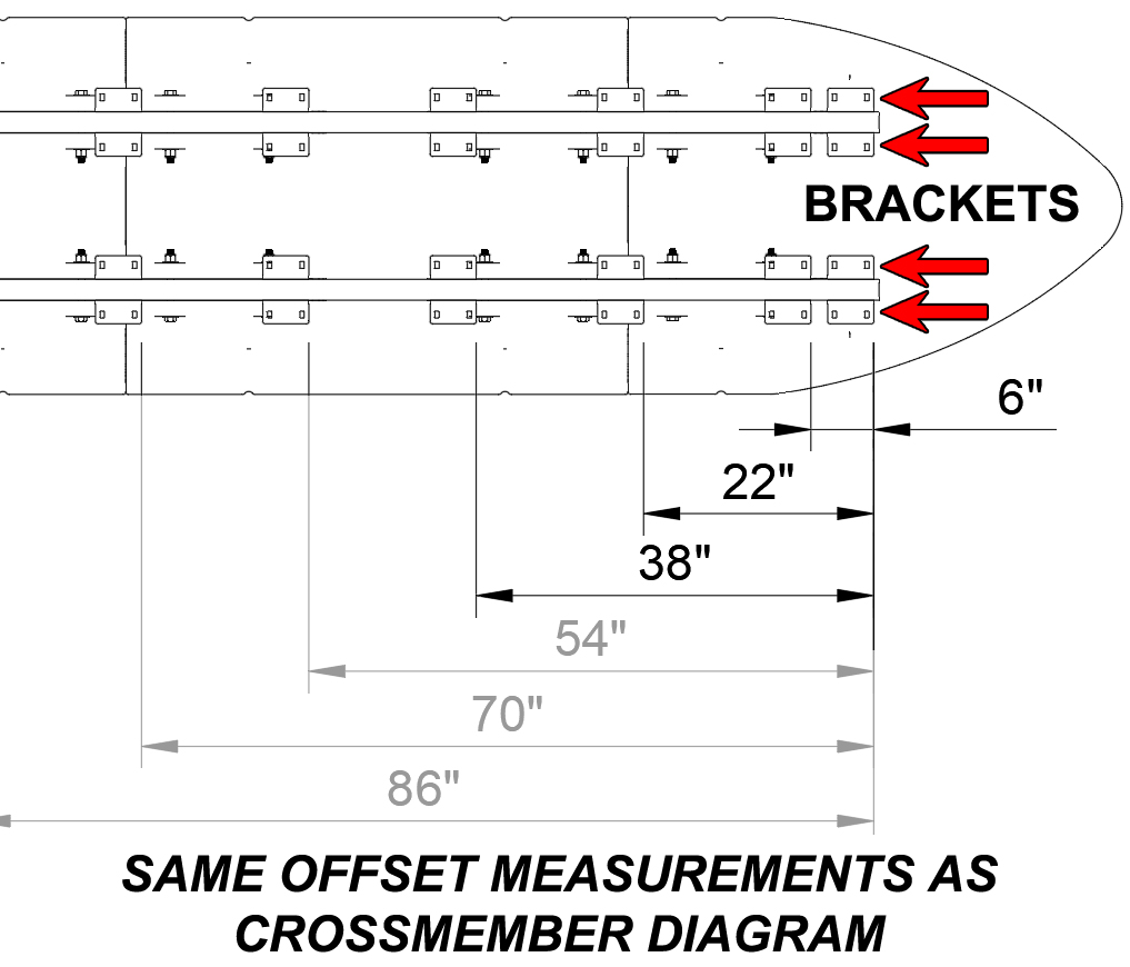
CROSSMEMBER PLACEMENT DIAGRAM NOTE #1
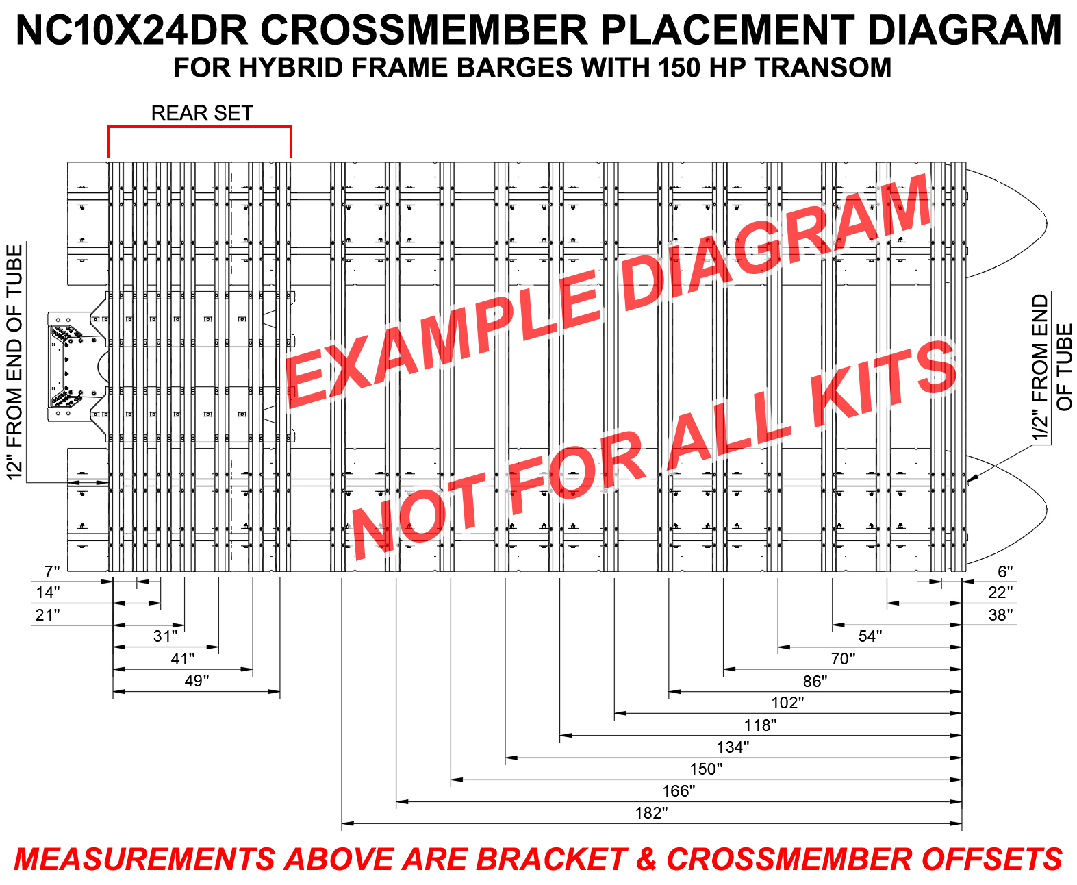
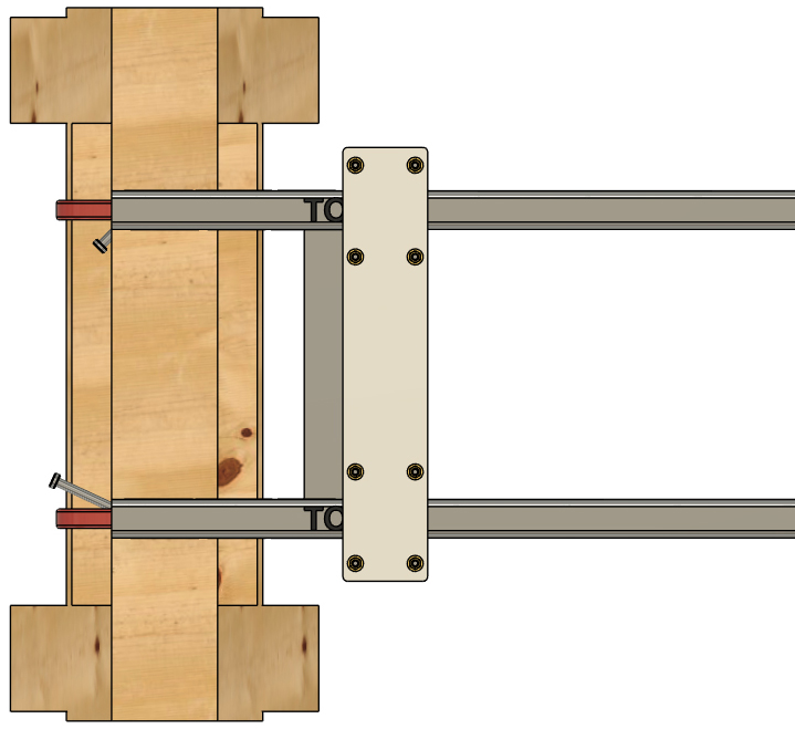
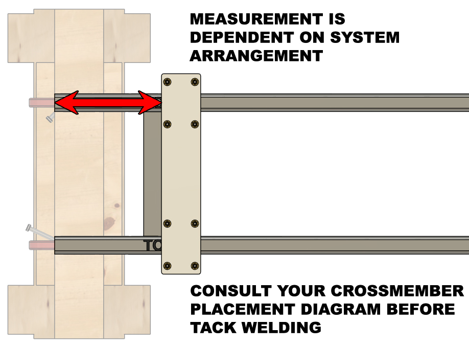
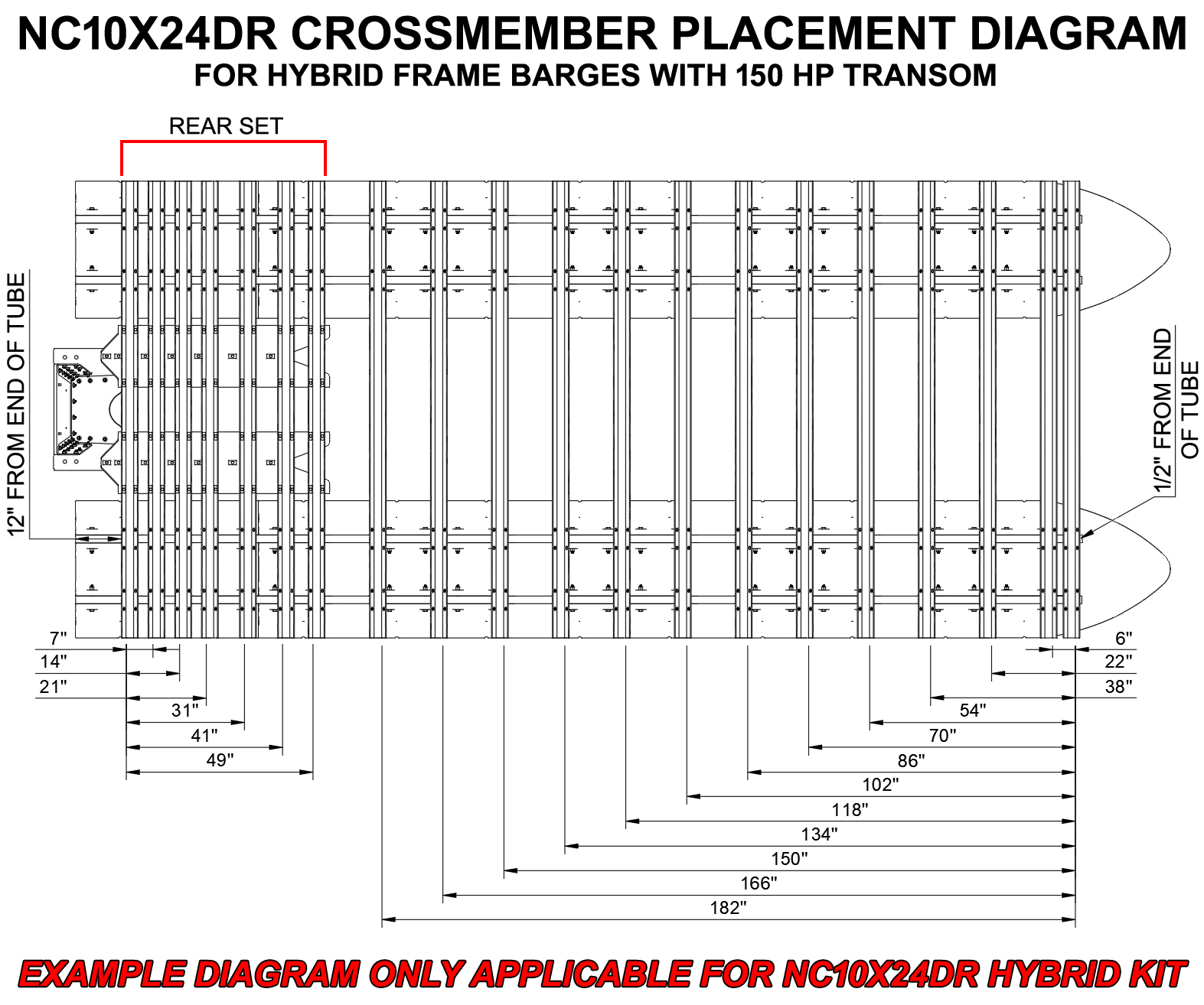
Moving forward, you will have to reference the CROSSMEMBER PLACEMENT DIAGRAM that was provided to you after the purchase of your kit. There are well over a 150 different arrangements that we can provide for our hybrid frame large barge kits, so there are simply too many diagrams to post them all here.
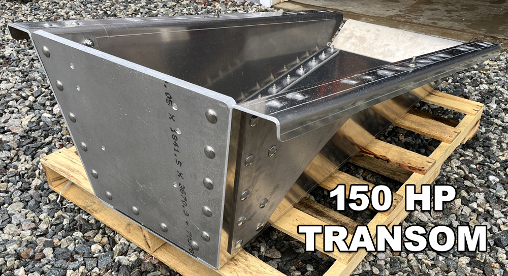
In this set of instructions, the example we are working through is a 10'x24' barge system with a 150 HP transom. The crossmember placement diagram we are working with is shown to the right and will only apply to this particular barge arrangement. We repeat, you must reference the diagram provided to you after your order is placed (or prior if requested). Your crossmember placement diagram shows all the hat channel crossmembers that will be bolted to your barge when it's completed. We need to note that the measurements at the bottom of the diagram show all the crossmember and bracket offsets. These measurements are the same, even if the drawing shows offset measurements from the top of the hat channel crossmembers. The crossmembers are the same width as the crossmember brackets. For instance, at the front of our example boat, we list first three crossmembers behind the frontmost crossmember as being offset by 6", 22", and 38". Below we have a close-up of this diagram without the crossmembers installed. As you can see, these measurements are identical. Please be aware of this when referencing your diagram for placement of your brackets as you move forward.
|
|
|
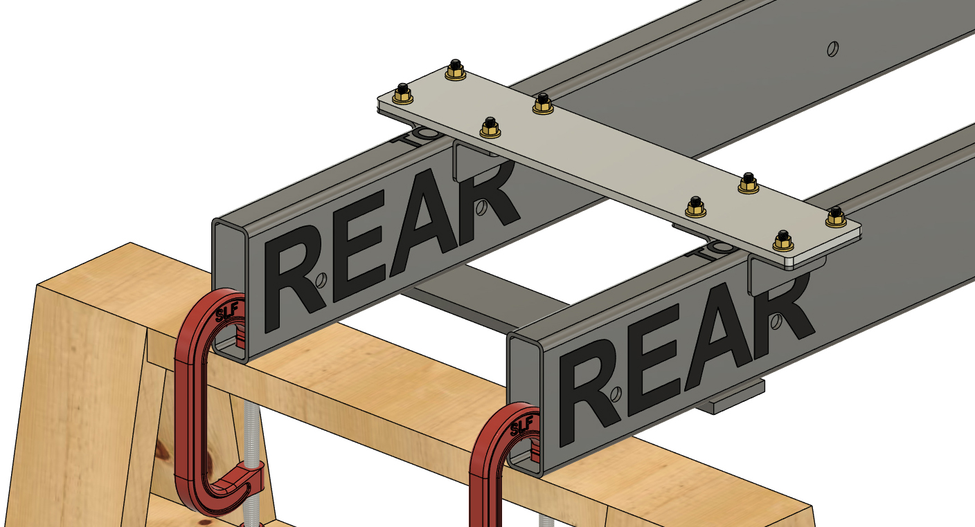
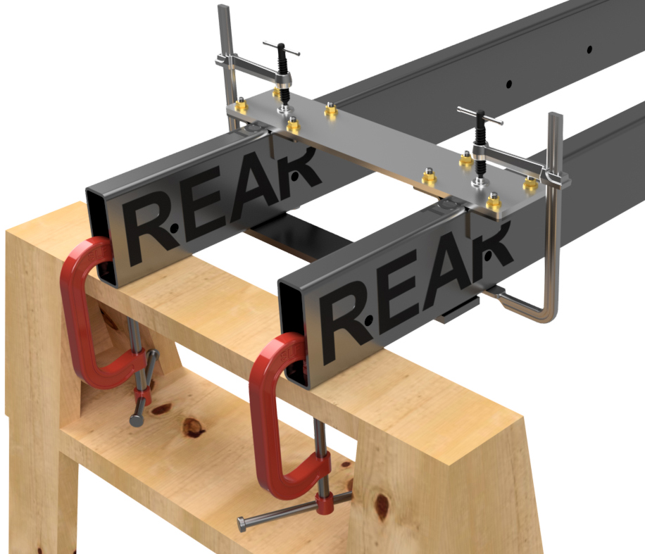
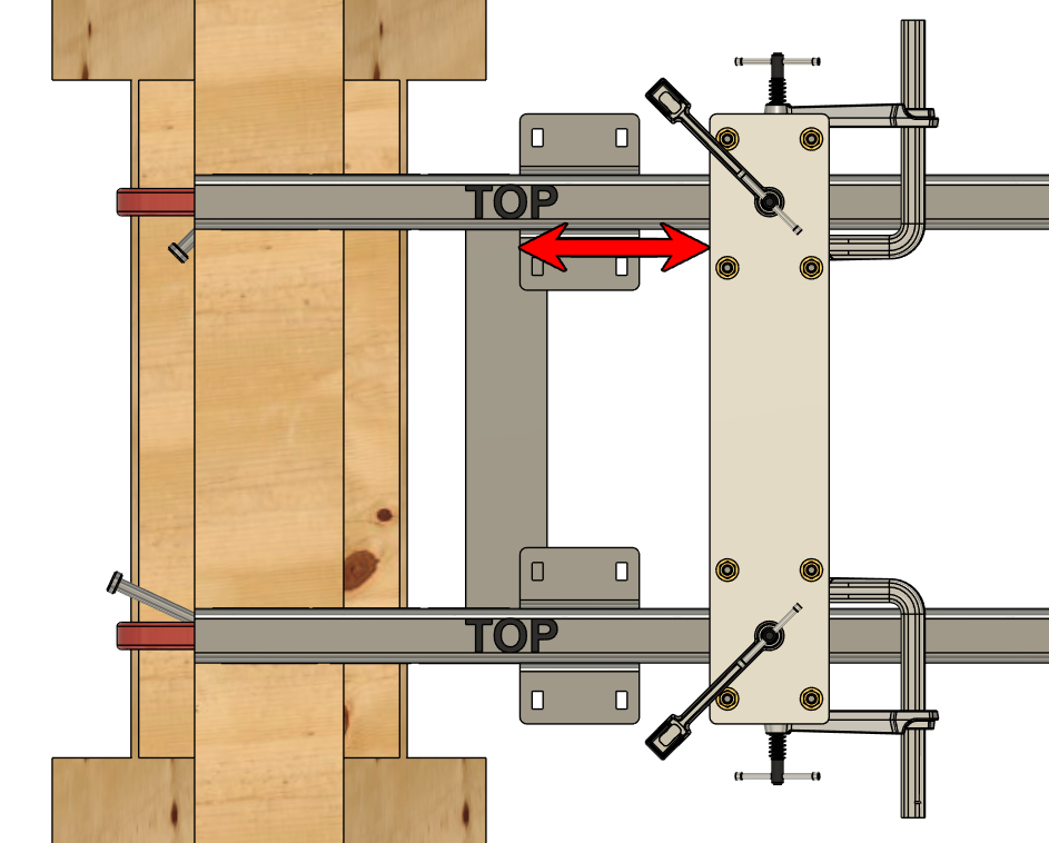
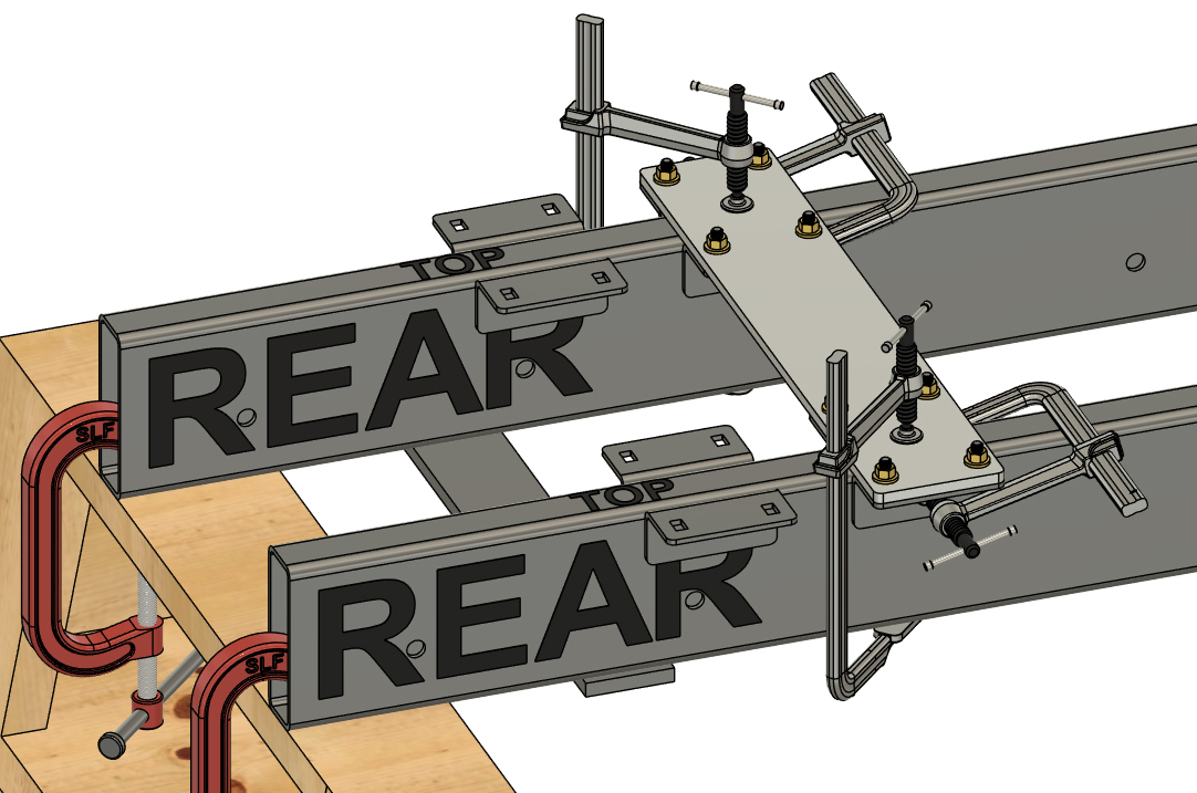
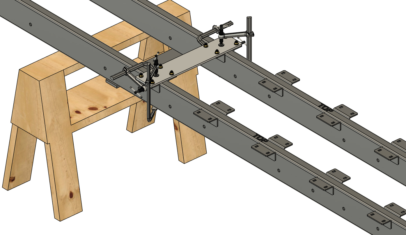
STEP 16
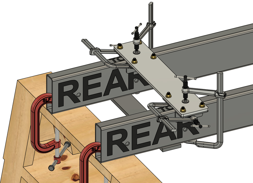
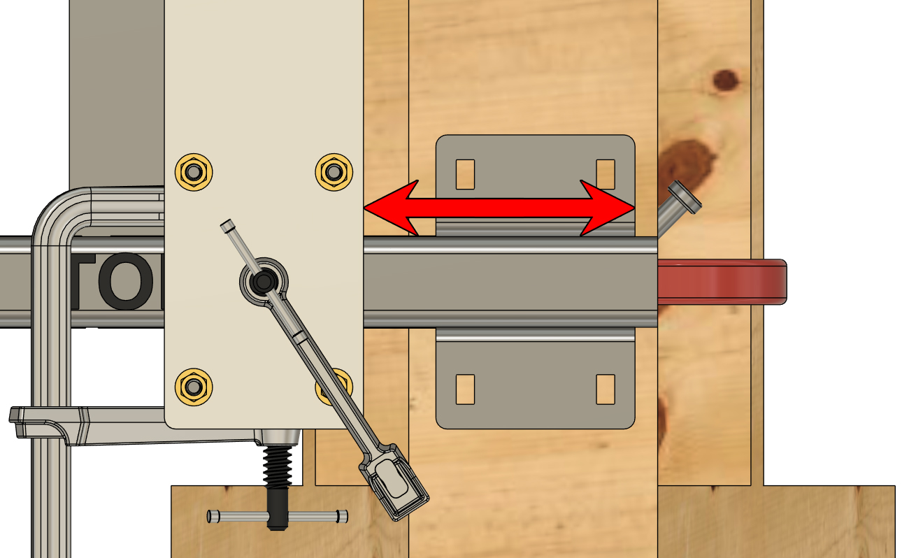
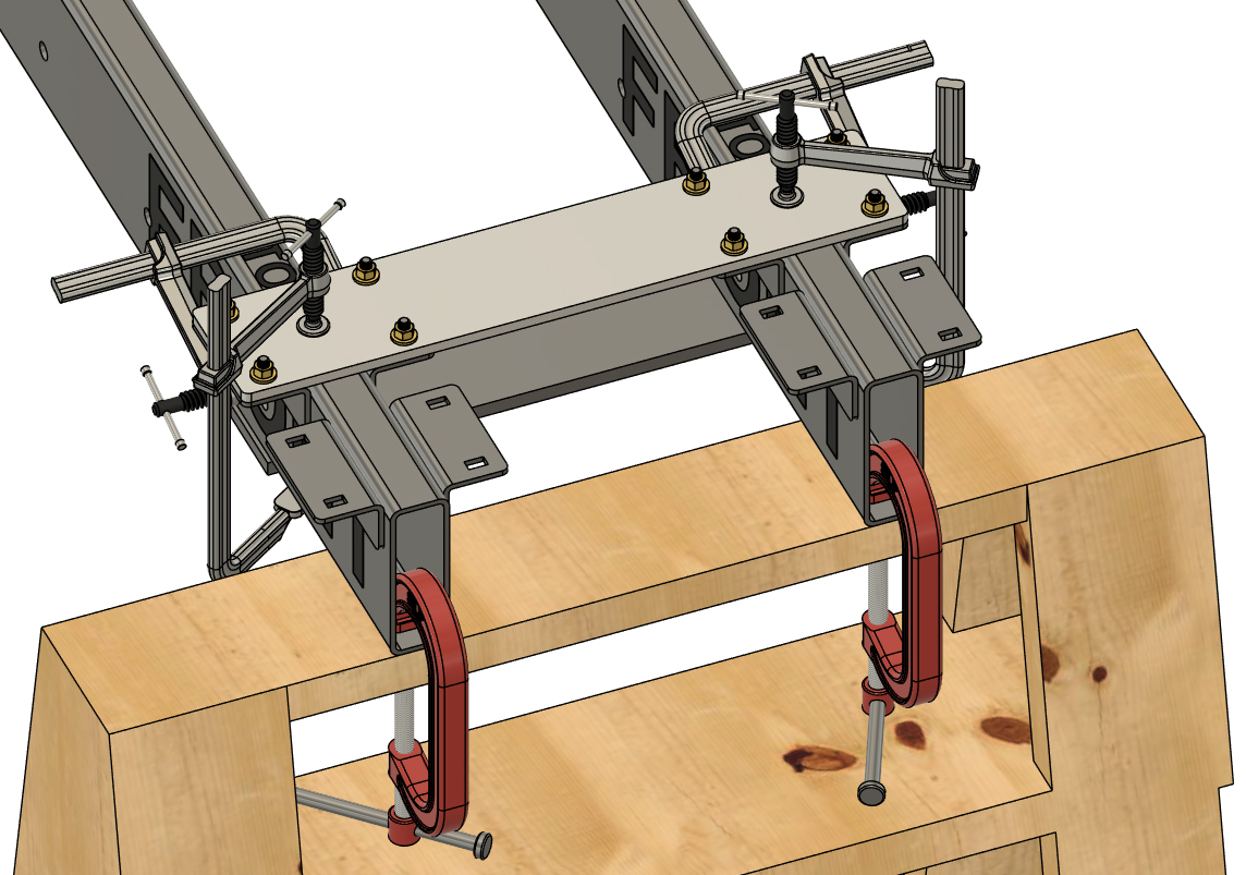
IMPORTANT: Our barge systems can have 2, 3, or 4 rows of floats and are also available with transom systems that go in-line with one or two centrally mounted pontoon assembly or assemblies. If your boat has two rows of floats, both pontoon assemblies will be identical. If you are building a boat with an in-line transom or transoms, such as a boat with 3 rows of floats and transom, the central set of floats will have crossmember brackets placed much further forward than the outside floats. Please be sure to consult your crossmember placement diagram when placing your brackets. If you have any questions whatsoever about this, CALL US AT 603-630-5658.
If you are currently building a short pontoon assembly that mounts ahead of a transom, move onto step 20. Central pontoon assemblies with an in-line transom do not have "REAR SET" crossmember brackets. The example we are working through in this set of instructions has 2 rows of floats that are each 24' long. These two pontoon assemblies are identical and each require that the rearmost set of brackets are placed 12" from the end of the frame tubes. This is a typical arrangement for our dual-row barges with our 150 HP transom. NOT ALL OF OUR BARGE SYSTEMS HAVE THIS ARRANGEMENT and you must consult your crossmember diagram for placement of your rearmost set of brackets. Once again, please be sure to be aware of which row of floats you are building as well. We recommond building outer pontoon assemblies first. Referencing your crossmember placement diagram, place your first "crossmember bracket jig assebly" onto the set of frame tubes in the position stated on your diagram. You are placing this on the "REAR" end of your frame tubes and the crossmember placement diagram will reference the position as "REAR SET". Use a square to ensure that the "crossmember bracket jig assebly" is square with your frame tubes. Double-check the measurement to the ends of your tubes and clamp the upper plate onto the frame tubes. Remember that proper placement of your crossmember brackets is vital for ease of proper assembly of your barge as a whole. Take your time and ensure that all bracket placement from this point forward matches your crossmember diagram. Slightly loosen the nuts and bolts and slide the angle brackets against the tubes and tighten the nuts and bolts (slight amount of torque on the nuts is enough). Install clamps on the vercical portions of the angle clamps as shown. Remember, it's most important that the upper plate is secure against the "TOP" surface of the frame tubes. Double-check that all 4 clamps are secure.
|
|
|
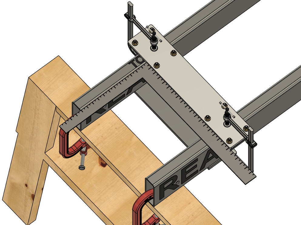
STEP 17
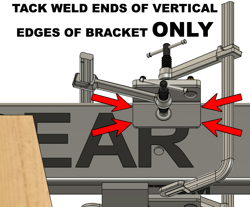
Tack weld each of the four crossmember brackets in place. Tack weld the end of the verical portion of each bracket in the positions shown. As we move forward, we will only weld on the vertical ends of these brackets. Adhering to this welding specification is vital.
|
|
|
STEP 18
Remove the hardware and aluminum jig plate from the welded brackets and assemble another "crossmember bracket jig assebly". Referencing your crossmember placement diagram, place the assembly the specified distance ahead of brackets you just welded on. Double-check all your measurements and clamp the "crossmember bracket jig assebly" to your frame tubes just as before. Tack weld the brackets in place as you did before.
|
|
|
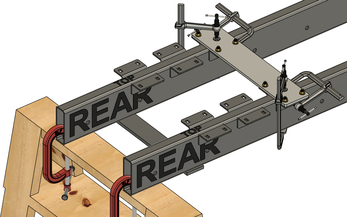
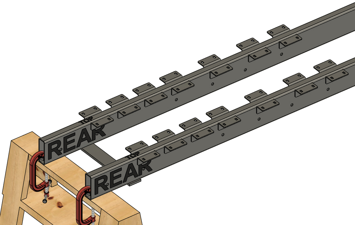
STEP 19
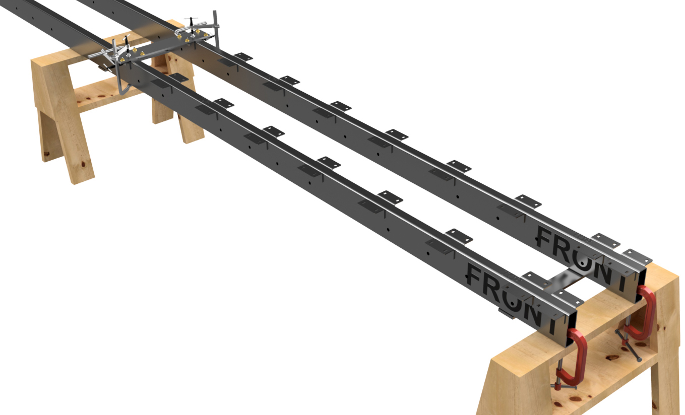
Continuing to reference your crossmember placement diagram, place and tack weld on the remaining "REAR SET" crossmember brackets until they are all in place. When you do this, remember that you are always measuring to the rearmost crossmember brackets, not the end of the tube. Also, ALWAYS DOUBLE-CHECK YOUR MEASUREMENTS BEFORE WELDING.
|
|
|
STEP 20
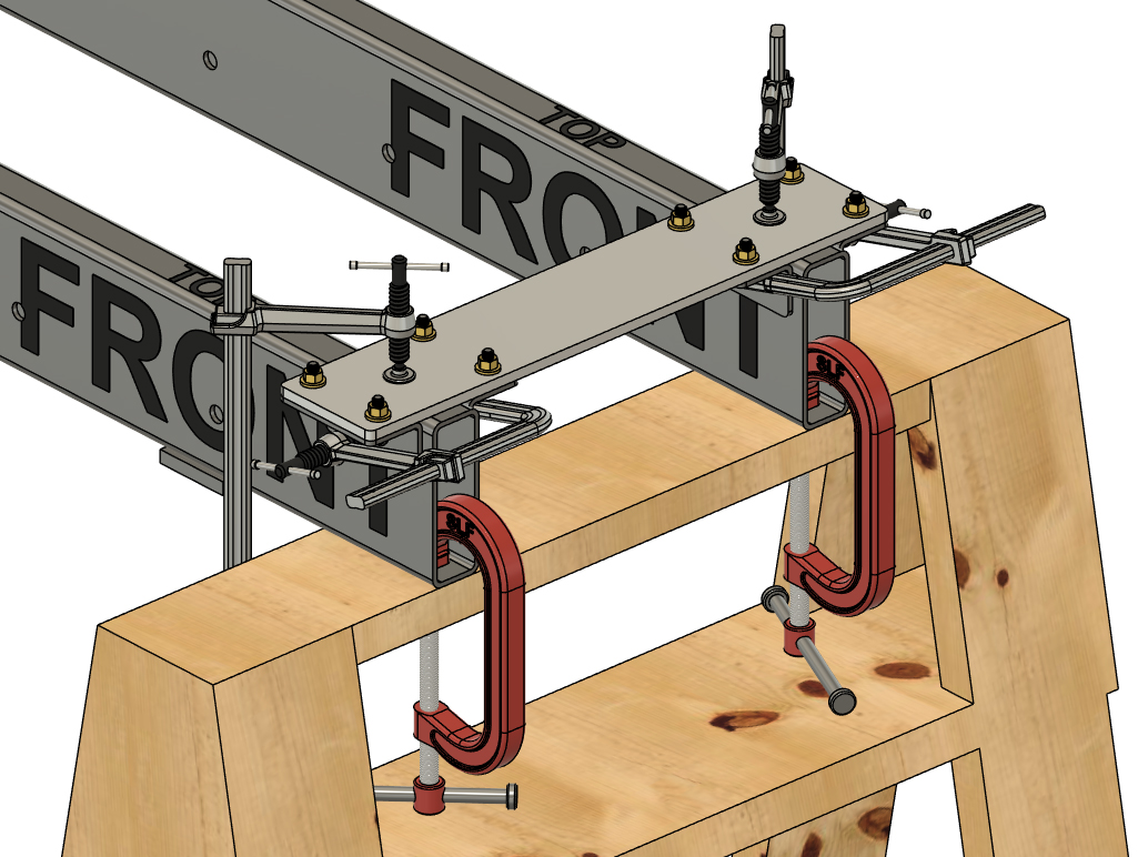
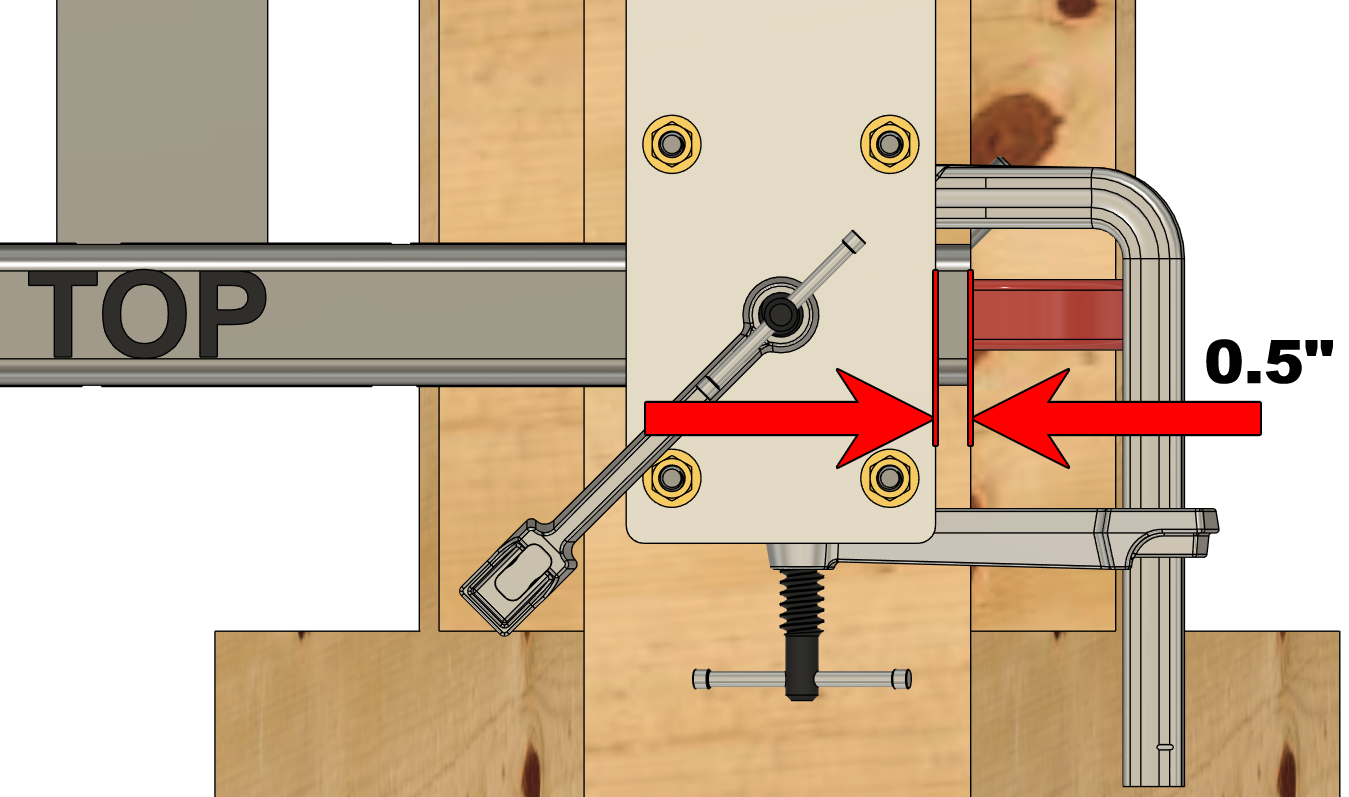
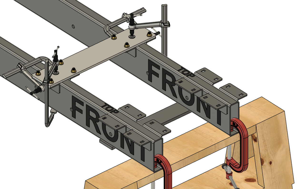
With your "REAR SET" crossmember brackets all in place, you can now move onto the FRONT end of the frame tubes. Assemble a "crossmember bracket jig assebly" and place the edge of the assembly 0.5" from the ends of your frame tubes. This measurement will be the same for every hybrid framed large barge system. Use your square to check that the aluminum plate for the assembly is square with the frame tubes and clamp the assembly in place as you did before.
Tack weld the crossmember brackets in place following the same procedure as before. Remove the aluminum jig plate and hardware. NOTE:
If all of your 6"x2" tubes are NOT cut accurately, you will have to adjust the placement of your crossmember brackets in this step. For instance, if you have a pair of frame tubes that are 1/8" longer than another pair, you will have to place your brackets 1/8" further back on the longer frame tubes. Ideally, the frame tubes for similar length pontoon assemblies will be the exact same length to avoid assembly challenges later on.
|
|
|
STEP 21
Referencing your crossmember placement diagram, assemble and place another "crossmember bracket jig assembly" in-line with the set of brackets you placed in step 20. As before, please be aware that you will be measuring to the frontmost set of brackets from this point forward, not the front of the frame tubes.
Clamp the "crossmember bracket jig assembly" in place, tack weld the brackets in place, and remove the aluminum plate. |
|
|
STEP 22
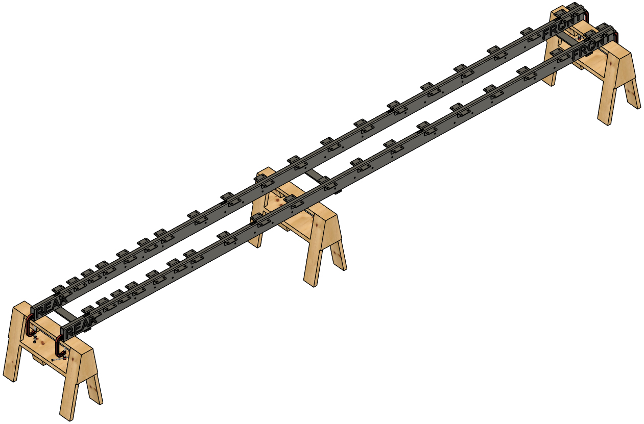
Continue to work your way backward on the set of frame tubes and install the remaining crossmember brackets, tack welding each one in place following the same procedure as before. Install brackets in every position pointed out in your crossmember placement diagram.
|
|
|
STEP 23
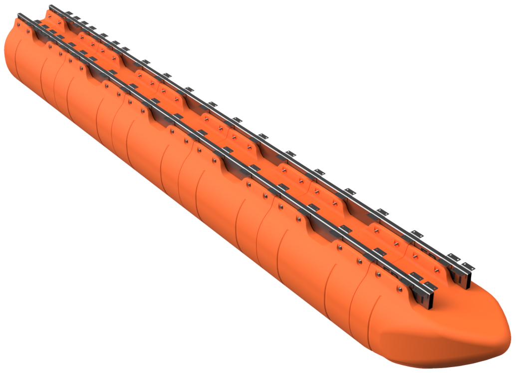
With all of your crossmember brackets in place, unclamp and flip over the frame tube assembly. Clamp it back onto your saw horses. The "BOTTOM" side of the frame tubes will now be facing upward.
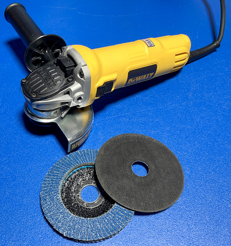
Using your angle grinder with a cut-off disk, carefuly remove the tack welds holding the 3/8" thick bars you tack welded to your tube assembly in step 13. After cutting the tack welds, use your flap sanding disk to grind the frame tubes smooth where any of the tack weld bead remains. If you are not yet building your last pontoon assembly, do the same with the bars you just removed.
|
|
|
STEP 24
NOTE:
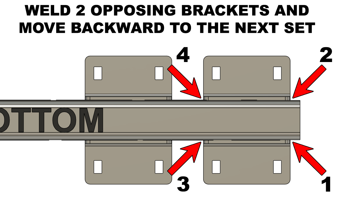
THE FOLLOWING WELDING PROCEDURE IS EXTREMELY IMPORTANT AND IS ONLY TO BE COMPLETED BY AN EXPERIENCED WELDER/FABRICATOR. FAILURE TO FOLLOW THIS PROCEDURE WILL CAUSE YOUR FRAME TUBES TO WARP, BEND, AND NOT REMAIN AS STRAIGHT AS NEEDED. IF YOU ARE NOT EXPERIENCED IN THE FIELD OF WELDING, DO NOT COMPLETE THE STEPS BELOW. THIS FINAL WELDING PROCEDURE IS TO BE COMPLETED WITH A TIG OR WIRE FEED LASER WELDING MACHINE. WE DO NOT RECOMMEND STICK OR MIG WELDING FOR THIS STEP. For the sake of clarity, we are only showing a single frame tube in our example pictures in this step. We recommend removing the clamps and for the final welding procedure so that the welds can be completed in the horizontal welding position. This means that you'll be placing the broad sides of the tubes upward and flipping the frame tube assembly many times during this step. Each crossmember bracket needs to receive a 3/16" gusset weld on each of the vertical ends of the part. We will NOT be welding the bottom or the top of the bracket. This is to avoid as much heat-soak and warping of the frame tubes as possible. Please review the diagrams and welding example pictures below showing exactly where the welds need to be made. As we move forward, we will be alternating sides of the tube as we weld the brackets in place. Always follow your next weld with a weld on the opposite side of the tube. You will flip the frame tube MANY TIMES during this procedure. Referencing the diagram to the upper right, start at position 1 at the "FRONT" end of the frame tube and weld the edge of the crossmember bracket in place. Flip the tube and weld position 2. Flip the tube and weld position 3. Flip the tube and weld position 4. Move backward to the next pair of brackets and follow the same procedure alternating sides of the frame tube for welding. Continue this process, moving backward on the tube, and weld every bracket in place. Remember to continue alternating sides of the tube as you weld on brackets to avoid warping. Repeat this procedure with the second frame tube.
|
|
|
STEP 25
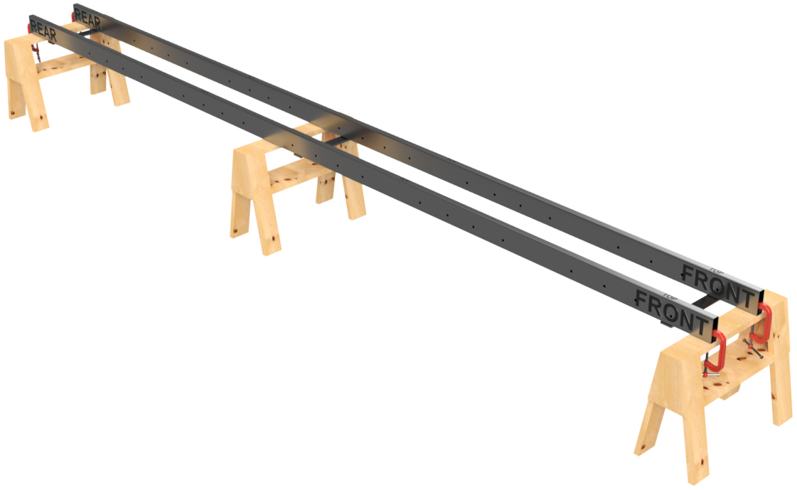
Place the two frame tubes so that the "BOTTOM" side of the tube faces upward with the matching ends pointing in the same direction. Loosely clamp the frame tubes in position as you had before so that they are about 14" apart again (16" on-center).
Matching the numbers on the float with the numbers on the tube, place the rearmost straight float onto the set of tubes and visually line up the bolt holes. Ajust the placement of the tubes and float if necessary and tighten the clamps onto the saw horses. Install ratchet straps once more if necessary to seat the float. In our example pictures, we have installed the straps. |
|
|
STEP 26
Just as you did in step 11, use your 5/8" drill bit mounted in your hand-held drill and drill through a single bolt hole to clear chips and then drive a 5/8" x 6 1/2" bolt with flat washer through the hole from the outside of the float. Drill through the next hole and drive in another bolt with washer. Do this on both sides of the float until all the bolt holes in the float have bolts. Just as before, when drilling, do so slowly, as your drill bit should only be clearing chips and verifying hole alignment, not drilling a new hole.
DO NOT INSTALL NUTS YET.
|

|
|
STEP 27
Match up the numbers for the next float forward and repeat step 26. Continue with all the remaining floats, including the nose cone, until all the floats are "pinned" onto the frame tubes. DO NOT INSTALL NUTS YET.
|
|
|
STEP 28
Just as you did in step 12, use a rag to clean any chips off of the bolts that have been driven through the bolt holes of the floats and frame tubes and loosely install STANDARD 5/8" STEEL nuts (NOT LOCK NUTS; DO NOT USE STAINLESS NUTS FOR THIS STEP OR THEY COULD JAM) onto the bolts as shown. These nuts are temporary.
|
|
|
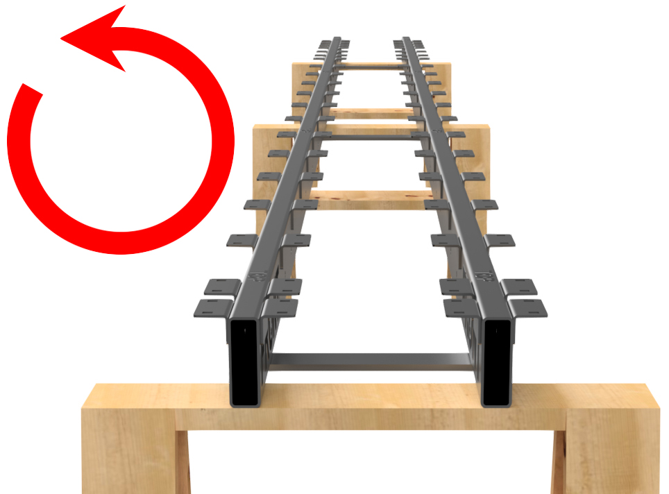
STEP 29
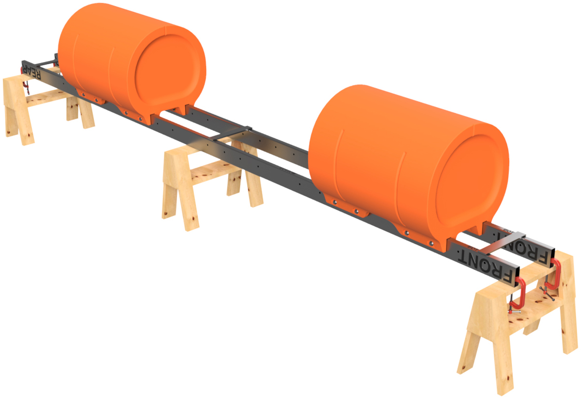
Remove the ratchet straps and unclamp the pontoon assembly from your saw horses. Using lifting equipment, remove the pontoon assembly from your saw horses and flip it so that the pontoon assembly is upright as shown ("TOP" of tubes face up). Place the pontoon assembly on a flat floor or work surface. If working on concrete or pavement, we recommend placing scraps of carpet or cardboard under the floats.
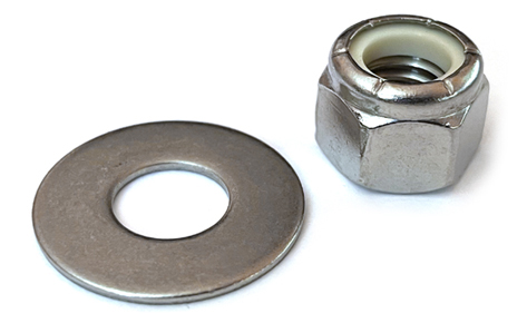
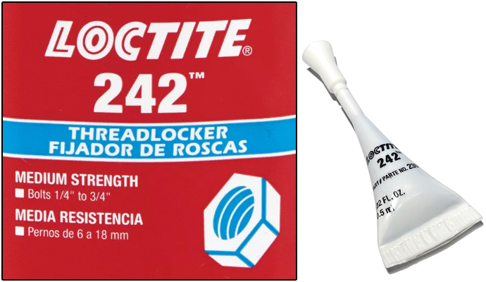
PLEASE USE EXTREME CAUTION WHEN LIFTING AND FLIPPING THE PONTOON ASSEMBLY. THIS IS THE HEAVIEST ASSEMBLY THAT YOU WILL BE WORKING WITH DURING YOUR BARGE BUILDING PROCESS. MOVE SLOWLY DURING THIS PROCESS TO ENSURE THAT YOU DO NOT BEND ANY CROSSMEMBER BRACKETS AS WELL. Remove all of the temporary standard 5/8" steel nuts from the bolts holding the floats. Place 5/8" flat washers over each of the bolts. DO NOT INSTALL THE LOCK NUTS YET. After shaking the container for a few seconds, apply a liberal amount (enough to go around 5-6 threads - start at the end of the bolt) of Loctite 242 (blue medium strength) to a float bolt and then install a 5/8" lock nut. Tighten the nuts until the mounting flanges on the floats start to flex inward. We do not have a torque specification beyond this. Install all the nuts on a single float and then move onto the next float until all the 5/8" float bolts have nuts installed. APPLICATION OF THE LOCTITE IS 100% REQUIRED FOR THE FLOAT BOLTS. THE LOCTITE LUBRICATES THE THREADS AND MAKES THE NUTS MORE SECURE. DO NOT SKIP THIS STEP OR YOUR 5/8" NUTS WILL JAM. WE REPEAT: DO NOT SKIP THIS STEP.
|
|

|
STEP 30
If you've reached this point, you've built at least one of your pontoon assemblies. Place your completed pontoon/pontoons aside and repeat Steps 1-29 until all of your pontoon assemblies have been built.
|
|
CROSSMEMBER PLACEMENT DIAGRAM NOTE #2:
The tough part of your build has been completed, so take a breath, enjoy a piece of the pizza we specified at the top of this page, and enjoy the rest of your project. The remaining part of the assembly is near impossible to mess-up!
Once again, moving forward, you will have to reference your crossmember placement diagram specific for your barge system. In this set of instructions, the example we are working through is a 10'x24' barge system with a 150 HP transom. The crossmember placement diagram we are working with is shown to the right and will only apply to this particular barge arrangement. We repeat, you must reference the diagram provided to you after your order is placed (or prior if requested). Your crossmember placement diagram shows all the hat channel crossmembers that are now to be bolted to your pontoon assemblies. Please note that the rearmost set of crossmembers for your barge are labeled "RS", and we reference them as the "Rear Set" of crossmembers. If you purchased a transom with your barge system, these crossmembers will have central bolt holes for mounting your transom system. If you did not purchase a transom, all the crossmembers will be identical and your diagram may not have "RS" labels on any of the crossmembers. |
|
|
FRAME & ACCESSORY FASTENER TORQUE SPECIFICATIONS
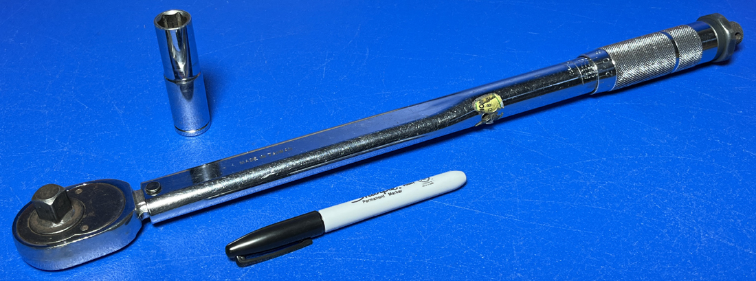
Each of the 3/8" or 7/16" nuts and bolts installed from this point forward require the proper amount of torque to ensure that they are fastened securely and retain full strength. The proper torque specifications for either hardware size is listed below.
3/8" nuts and bolts: 55 foot pounds 7/16" nuts and bolts: 60 foot pounds From this point forward when we say to fully torque or fully tighten a bolt or nut, we are referring to the specifications above. Also, it is good practice to draw a line on the head of a bolt with a marker after it has been torqued to specification. This makes it very easy to do a visual inspection to ensure that you didn't miss any fasteners. If you do not own a torque wrench or do not want to purchase one for your assembly, many autopart stores will allow you to borrow one at little or no cost. USE OF A TORQUE WRENCH ON ALL THE FASTENERS FROM THIS POINT FORWARD IS NOT OPTIONAL. FAILURE TO PROPERLY TORQUE ANY FASTENER FROM THIS POINT FORWARD WHEN INSTRUCTED CAN CAUSE FRAME SYSTEM FAILURE. |
|
|
STEP 31
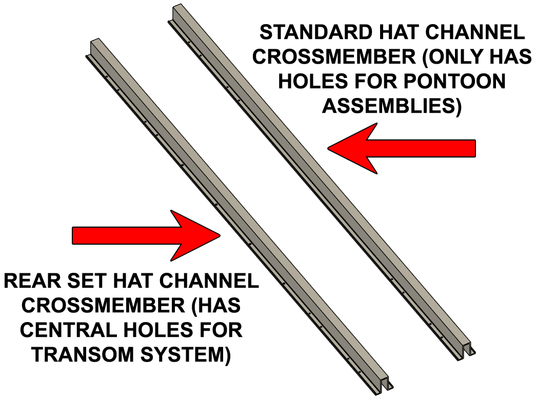
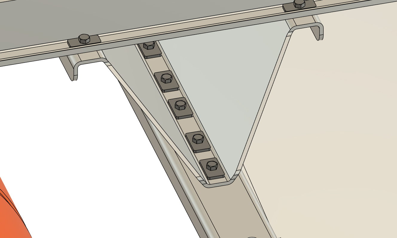
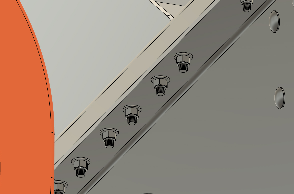
We can now start installing crossmembers across the floats. If you purhcased a transom with your barge system, you will have received hat channel (or HD flange tube) crossmembers with two different hole patterns. If this is the case, your crossmember placement diagram will list "Rear Set" on the rearmost 5-7 crossmembers. These crossmembers have centrally mounted holes that are machined to line-up with your transom system. If you are building a boat with 2 rows of floats, the differences will be very obvious. If you purchasea a kit with 3 or 4 rows of floats AND a transom, the "Rear Set" crossmembers will come labeled. If you DID NOT purchase a transom with your system, all the crossmembers will be identical any any crossmember can be placed in any of the positions listed on your crossmember placement diagram. We will refer to any crossmembers that are NOT "Rear Set" crossmembers as "standard crossmember" from this point forward.
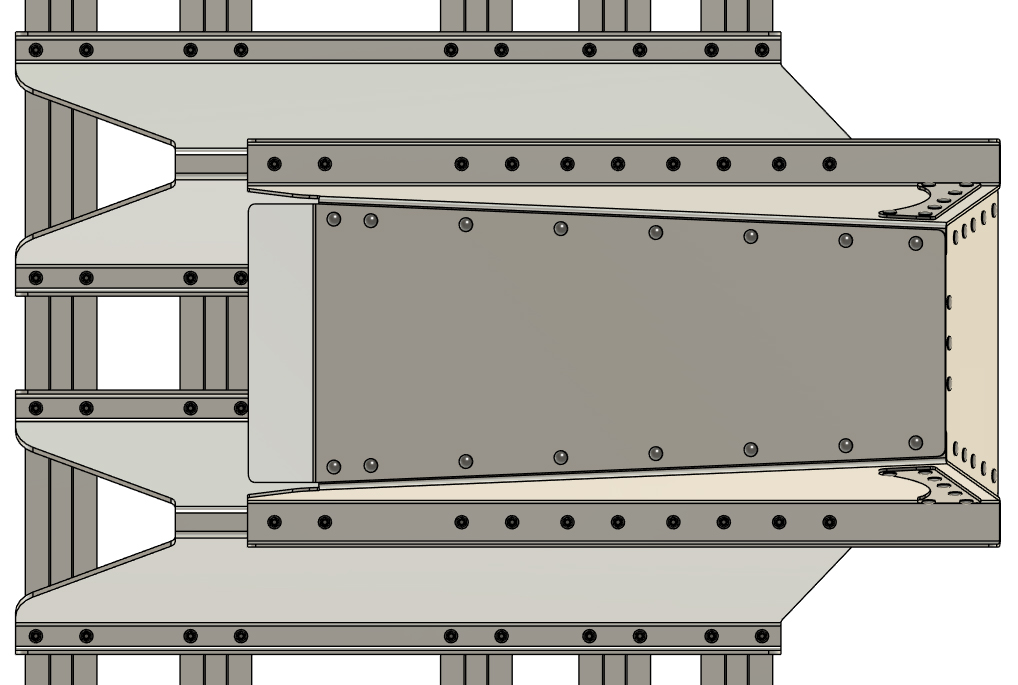
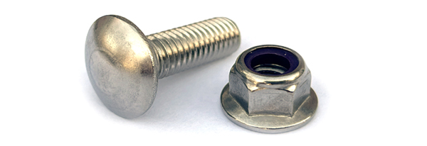
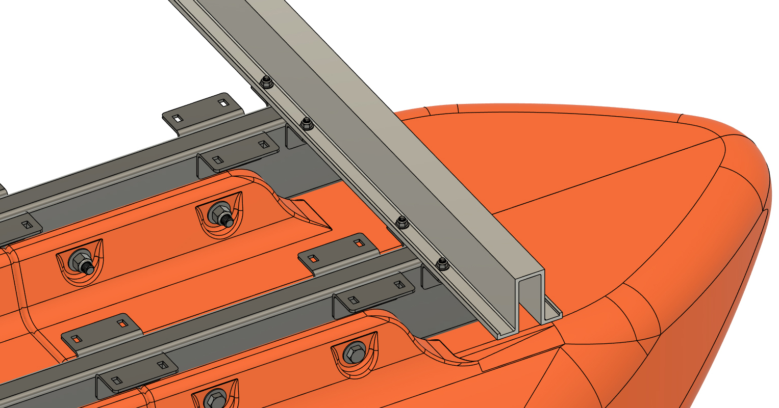
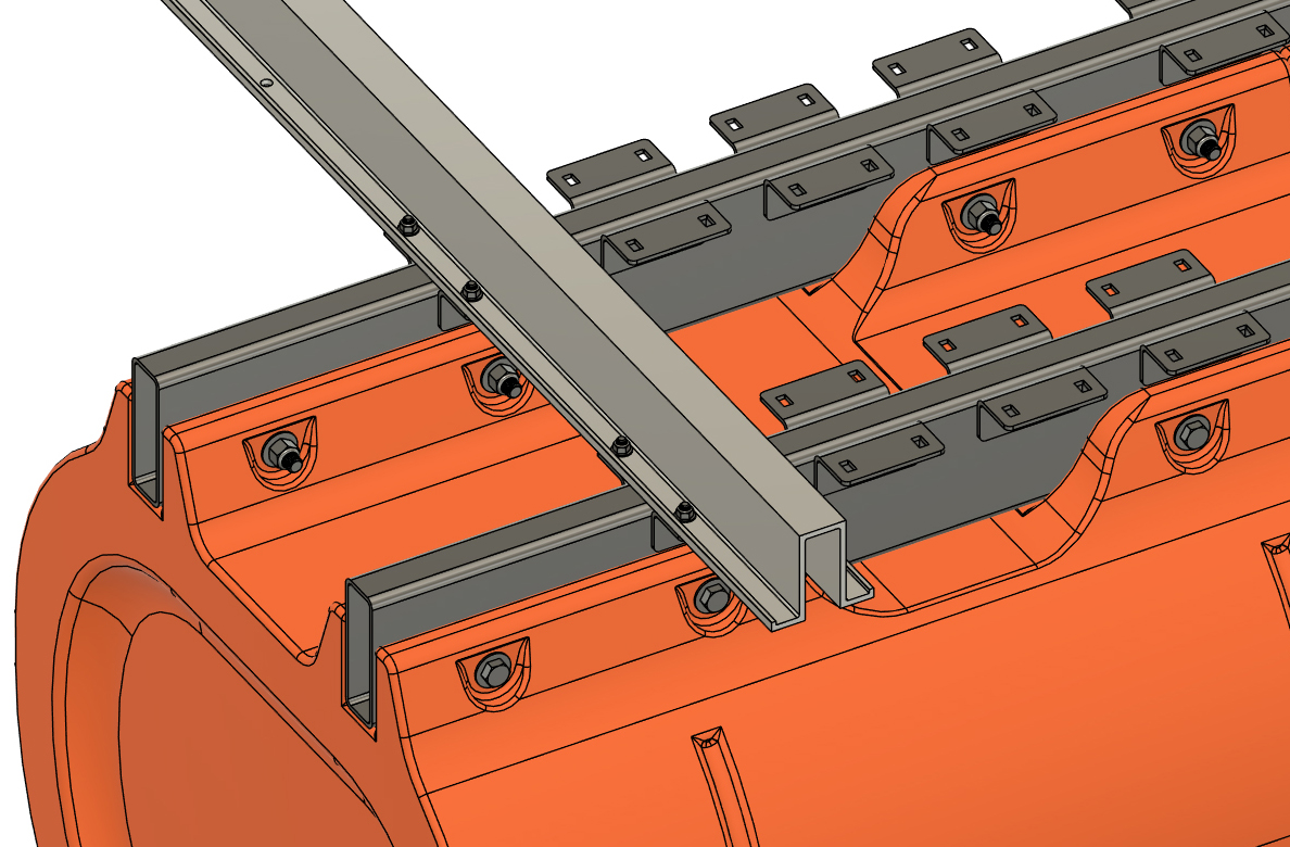
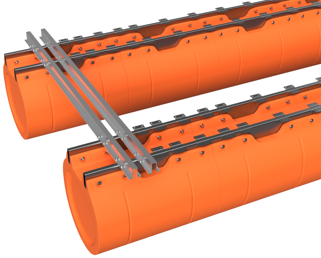
With your two pontoon assemblies held upright, place a "Rear Set" crossmember across the rearmost crossmember bracket position of each pontoon assembly. You will have to adjust the positions of your pontoon assemblies to line up the bolt holes. Use 3/8" x 1" carriage bolts and 3/8" flange lock nuts to LOOSELY bolt the crossember to you two pontoon assemblies. When doing this, the carriage bolts goes upward through the rectancular brackets and the flange lock nut sits on top of the crossmember's flanges. Ensure that each crossmember bracket you're attaching to has 2 bolts and nuts and leave the bolts loose. Loosely install a standard hat channel across the frontmost bracket sets of your pontoon assemblies as well. DO NOT TIGHTEN THE NUTS AND BOLTS YET NOTE:
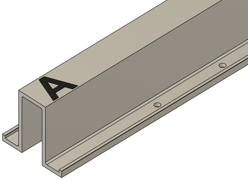
Crossmembers have "A" written on one end. As you move foward, place the "A" on the right side (starboard side) of the barge. When the hole pattern is machined in each crossmember, this is the end that is referenced on the machine cutting the holes. Placing the "A" end of all the crossmembers on the same side of the boat ensures perfect alignment of all the mounting holes and is important as we move forward.
|
|
|
STEP 32
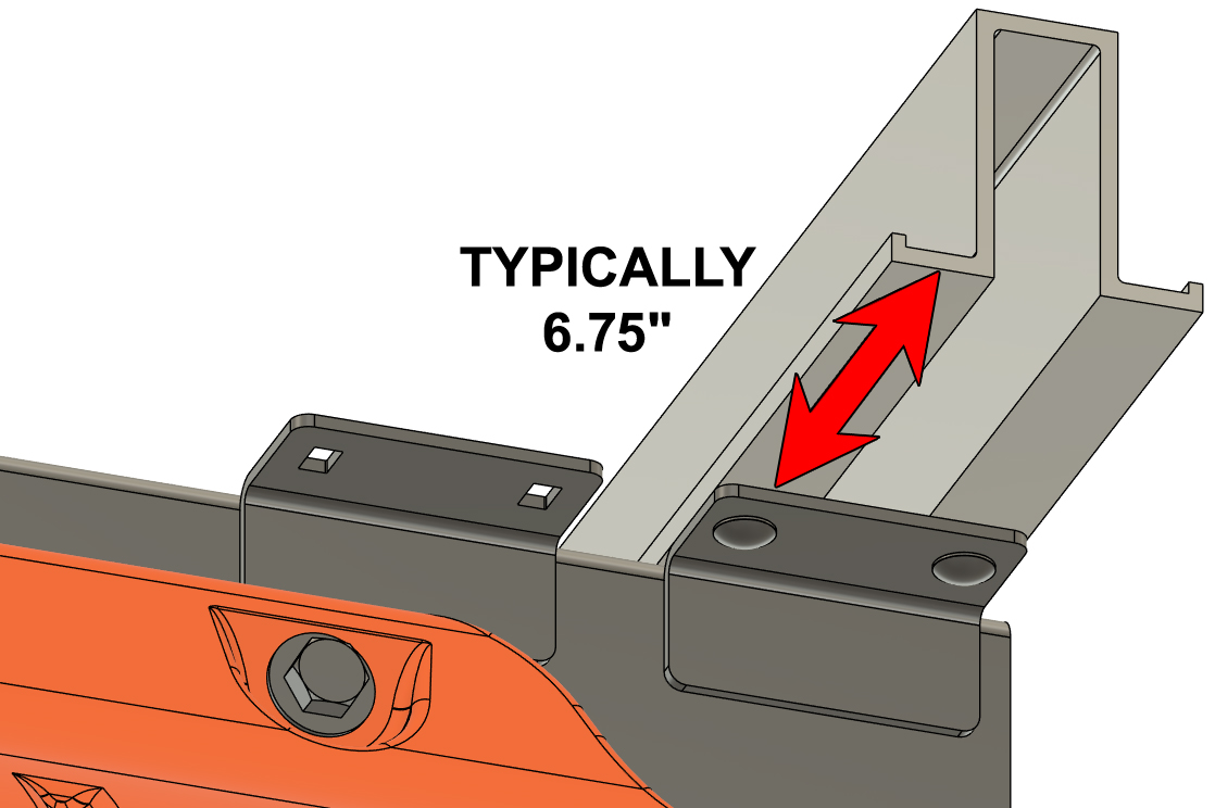
The welded-on crossmember brackets have slotted bolt holes to allow for variations with our floats (mounting channels are 16" on-center +/- 3%). Starting at the right rear corner of the boat (starboard stern), measure and adjust the placement of the crossmember so that the end is 6.75" from the top edge of the crossmember bracket as shown in the diagram to the right. If you are not quite able to get that measurement, adjust to as close as you can. Use your square to verify that the crossmember is square with the attaching pontoon frame tube and hand-tighten the carriage bolts and nuts for that end of the crossmember.
Move to the front of the boat on the same side. Adjust the crossmember so that the end is the same distance to the outer crossmember bracket as the measurement before, check for squareness to the pontoon frame tube, and hand-tighten the carriage bolts and nuts for that end of the crossmember. Move to the other side of the boat and repeat the process for the front and rear crossmembers. Be sure to only hand-tighten the nuts and bolts at this point. |
|
|
STEP 33
Working your way forward, place and very loosely bolt your remaining "Rear Set" crossmembers onto your floats. Measure and adjust the right ends of your crossmembers as you did in step 32. If you purchased a transom, DO NOT TIGHTEN THE NUTS AND BOLTS YET. If you did not purchase a transom, loosely tighten the nuts and bolts (do not "fully-torque" them yet).
|
|
|
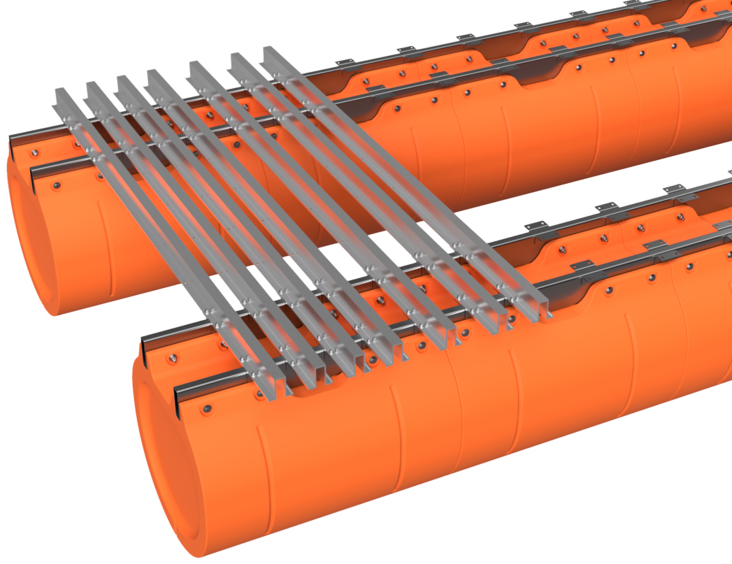
STEP 34
Working from the front of the barge backward, bolt on the remaining standard crossmembers as you've been doing. Measure as you did in step 32 and loosely tighten the nuts and bolts (do not "fully-torque" them yet).
|
|
|
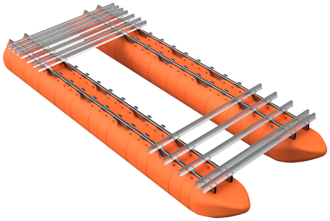
STEP 35
Starting the front of the vessel, work your way backward on one side and torque every nut and bolt holding your crossmembers. IF YOU PURCHASED A TRANSOM, DO NOT TORQUE THE NUTS FOR THE "REAR SET" CROSSMEMBERS YET. Be sure to NOT torque the nuts to more than the specified 55 foot pounds. After torquing a nut, use a marker to draw a line across the end of the bolt. This is a clear indication that the nut has been torqued. Move to the other side of the boat and repeat the process. Visually double-check that every crossmember bolt has been torqued to specification.
If you DID NOT purchase a transom, your kit is now completed! If you DID purchase a transom system with your barge kit, move onto the transom installation instructions below. As we offer two transom systems for our large barges, we have installation instructions for our 150 HP and 30 HP capacity systems below. Please be sure to reference the instructions that are appropriate for your system.
|
|
|
150 HP TRANSOM SYSTEM INSTALLATION
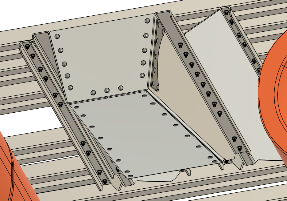
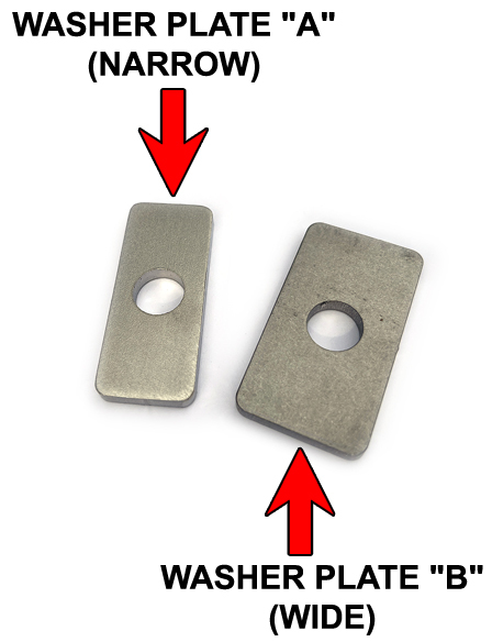
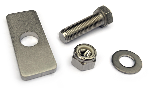
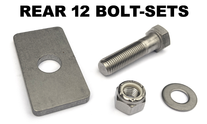
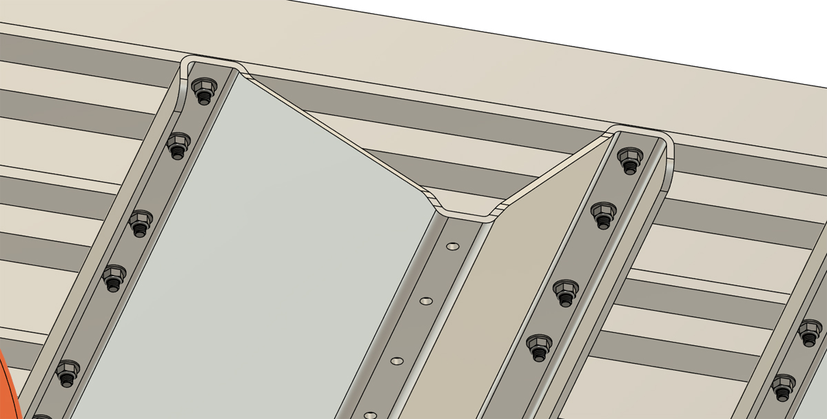
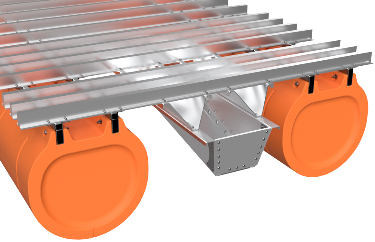
Our 150 HP transom system is installed using specialty 7/16" stainless hardware. The hardware is included with our system, but you do have to provide your own medium strength LocTite threadlocker (blue LocTite 242). For this portion of your project, the LocTite is 100% required. The harware that comes with your system includes 1 1/2" and 1 3/4" long bolts, washers, lock nuts, and 2 different 1/8" thick plates that we refer to "Washer Plates". Below we show the two plates. We will refer to the narrow plate as "Washer Plate A" and the wider plate as "Washer Plate B".
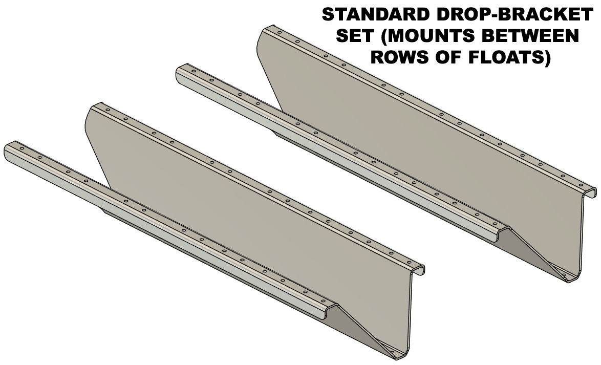
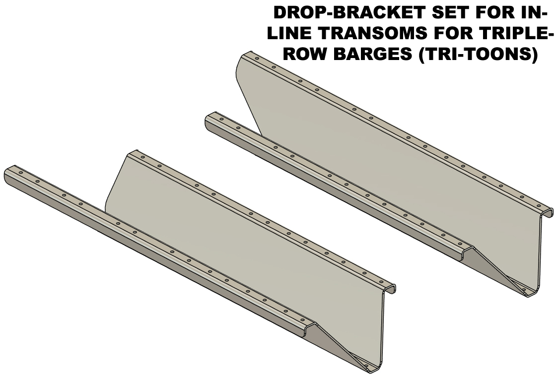
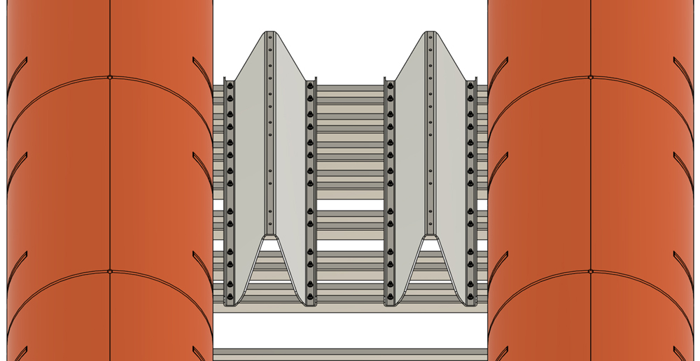
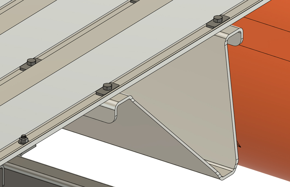
Due to the height of our 36" wide floats, our transom systems make use of formed 1/4" thick plates that we refer to as "drop-brackets". These brackets mount the transom itself down from the deck to allow long-shaft motors to be used on our barge systems. If your barge has 2 or 4 rows of floats, your transom system will include our "standard" design drop-brackets and the two brackets will be identical. If you are building a 3-row barge (tri-toon), and your transom goes in-line with your central row of floats, you will receive drop-brackets that have 2 fewer bolt holes on one side and are designed to fit around a central row of floats. These two brackets will be mirror images. 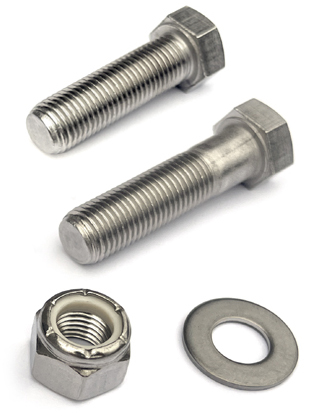
|
|
|
150 HP TRANSOM SYSTEM
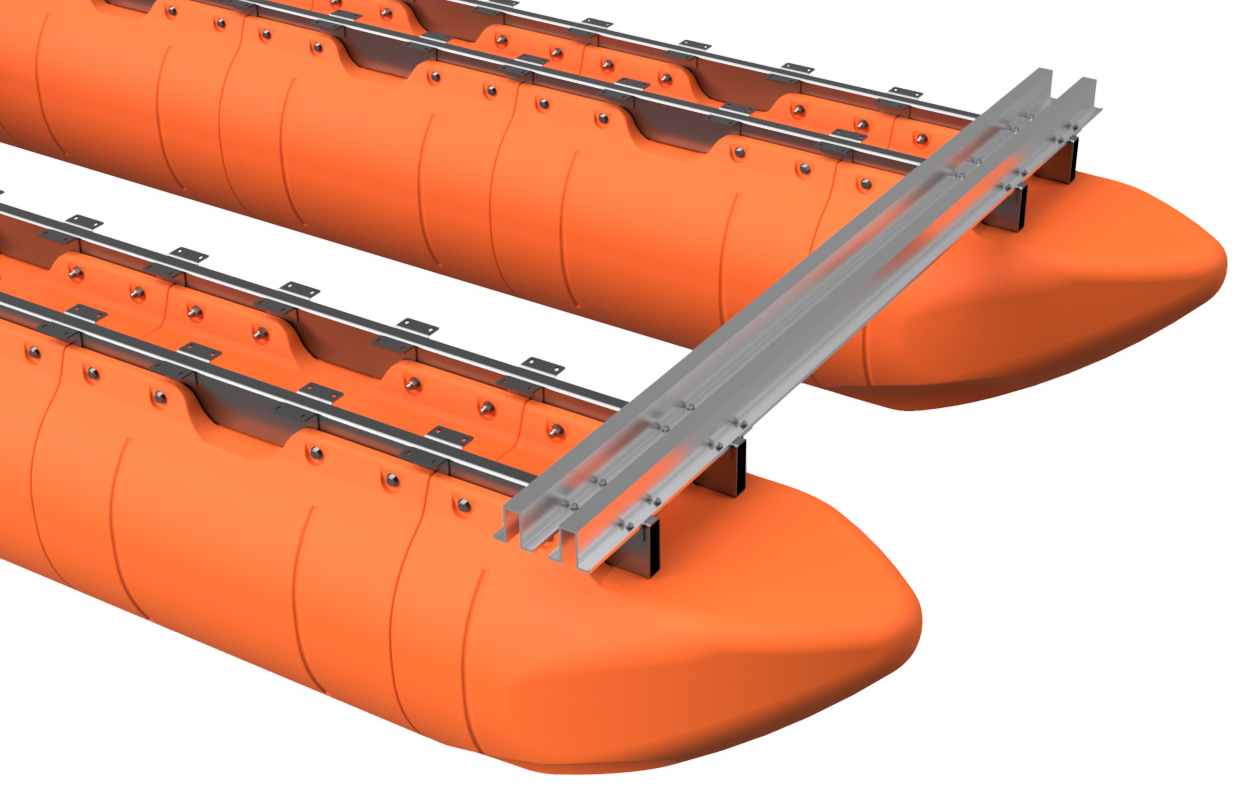
STEP 1 Select the 7/16" x 1 1/2" hex bolts (all of them), 56 of the 7/16" lock nuts, 56 of the 7/16" SAE flat washers, and all of the narrow washer plates (washer plate "A"). This group of hardware will be used to mount your transom drop-brackets.
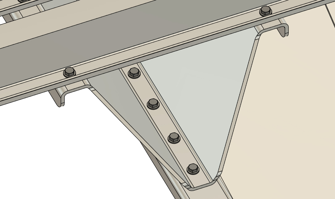
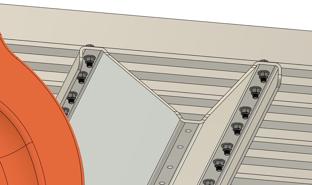
Insert a bolt with a narrow washer plate into the frontmost and rearmost 4 bolts holes in your "Rear Set" crossmembers. With the 8 bolts hanging down through the holes, position the two drop brackets so that the bolts hang through the frontmost and rearmost holes as shown. If working alone, a ratchet strap can hold brackets in position. Please note that the drop-brackets taper outward beyond the rear of the deck as shown. If you are installing an "in-line" transom on a triple-row (tri-toon) barge, the shorter upper bolt flanges of your drop-brackets face inboard. It'll be obvious as you can't install them otherwise. Install a 7/16" lock nut with LocTite applied to the threads, along with a 7/16" SAE flat washer onto each of the bolts hanging through the drop-brackets. Tighten the nuts and bolts just enough so the brackets can still wiggle. Install the same hardware through the remainder of the Rear Set crossmembers and upper flanges of the drop-brackets. Leave the hardware a bit loose for now and DO NOT FULLY TIGHTEN THE 7/16" BOLTS YET.
|
|
|
150 HP TRANSOM SYSTEM
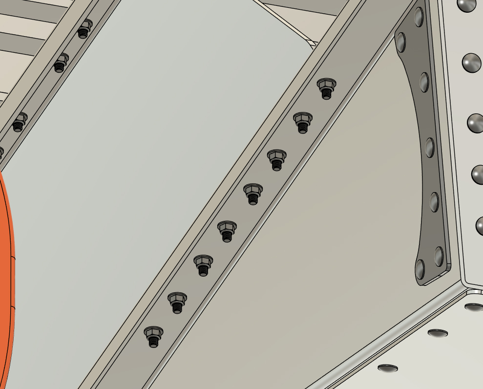
STEP 2 The transom gets bolted to the drop-brackets with 7/16" x 1 1/2" and 7/16" x 1 3/4" bolts, wide washer plates (washer plate "B"), flat washers, and lock nuts. Just as before, make sure to apply LocTite to the nuts before installation. The 12 rearmost transom bolt holes (6 per side) use 1 3/4" long bolts (due to the 1/4" thick stainless reinforcement plates) and the frontmost 12 holes (6 per side) use 1 1/2" long bolts.
Insert a 7/16" x 1 3/4" bolt with wide washer plate through the rearmost bolt hole of each of the drop-brackets, and then a 7/16" x 1 1/2" bolt with wide washer plate through the frontmost bolt hole of each bracket. Lift the transom up against the drop brackets and line up the hanging bolts with the rearmost and frontmost bolts holes in the top of the transom. Just as in the prior step, loosely install a nut with LocTite applied and 7/16" SAE flat washer onto each hanging bolt. Mostly tighten the bolts so the transom can still wiggle. Install the same hardware through the remainder of the bolt holes in the drop-brackets and transom. Remember, the front 6 holes on either side of the transom get the shorter bolts. Hand-tighten every mounting bolt and nut for the transom and drop-brackets and then fully torque every one of the 7/16" bolts to 60 foot pounds. DO NOT TORQUE BEYOND 60 FOOT POUNDS. Just as before, draw a line on every bolt with a marker after you fully torque it. After torquing every bolt to specification, visually check that you did not miss any. Fully tighten and torque all the nuts and bolts that fasten the Rear Set crossmembers to the pontoon assemblies (55 foot pounds). Draw the lines as before to indicate that you torqued each nut and bolt. Inspect that all your crossmember bolts have been torqued and your large barge frame, floats, and transom system is now complete! 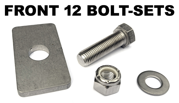
|
|
|
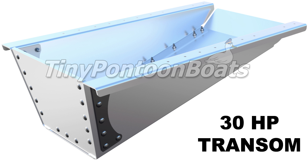
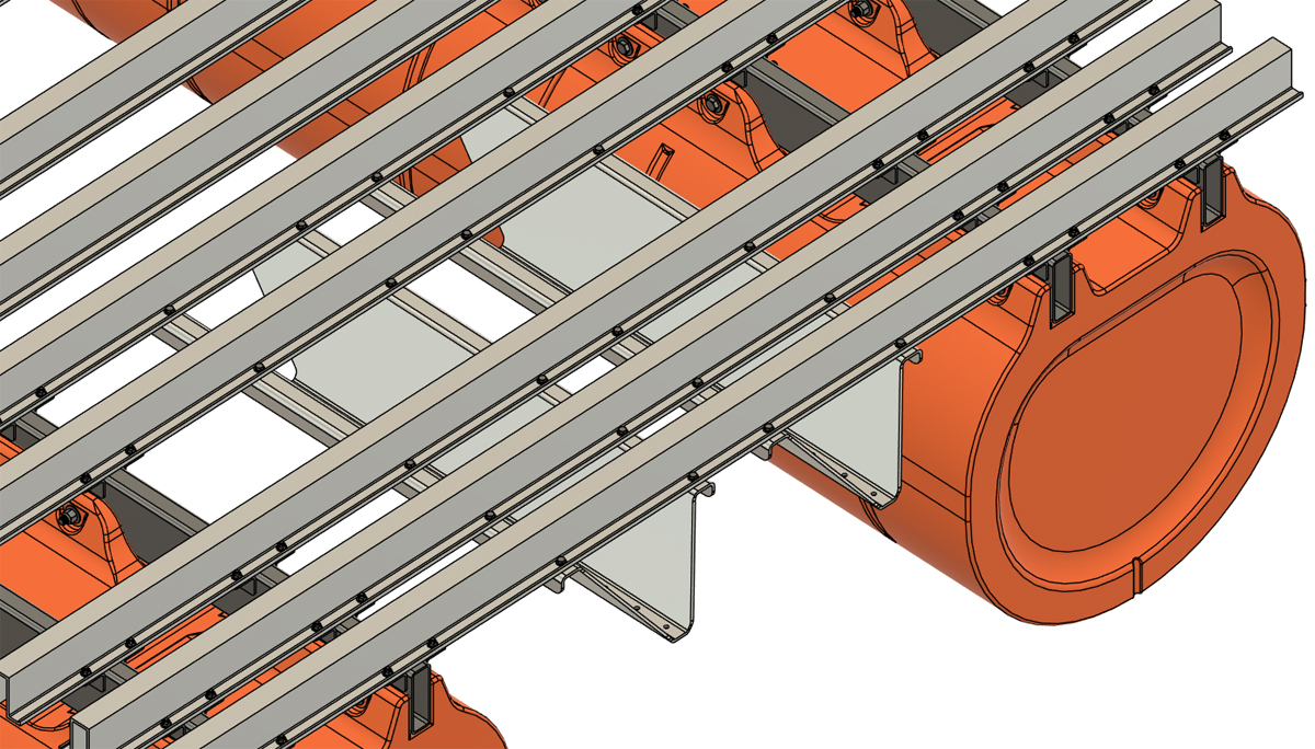
30 HP TRANSOM SYSTEM INSTALLATION
Our 30 HP transom system is installed using standard 3/8" stainless hardware. The hardware is included with our system, but you do have to provide your own medium strength LocTite threadlocker (blue LocTite 242). For this portion of your project, the LocTite is 100% required. The hardware that comes with your system includes 3/8" x 1 1/4" hex bolts, SAE flat washers, and flange lock nuts. Every bolt hole from this point forward receives the same hardware.
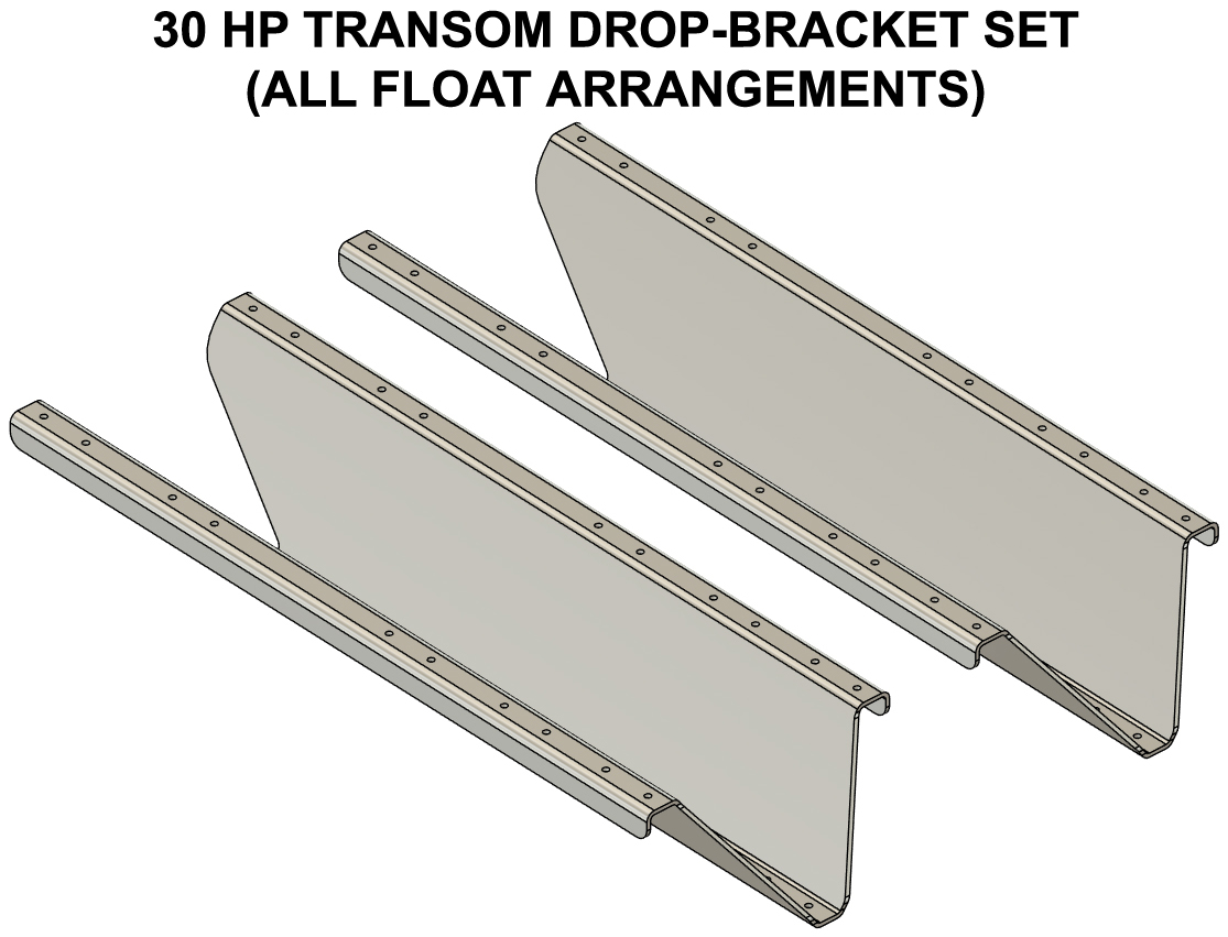
Due to the height of our 36" wide floats, our transom systems make use of formed 1/4" thick plates that we refer to as "drop-brackets". These brackets mount the transom itself down from the deck to allow long-shaft motors to be used on our barge systems. In some very specific applications, you may have to use an extra-long shaft motor or a jack plate with this arrangement (very light loads on large barges). When it comes to our 30 HP transom system, the drop-brackets are identical parts, no matter the number of pontoon assemblies your barge is equipped with. 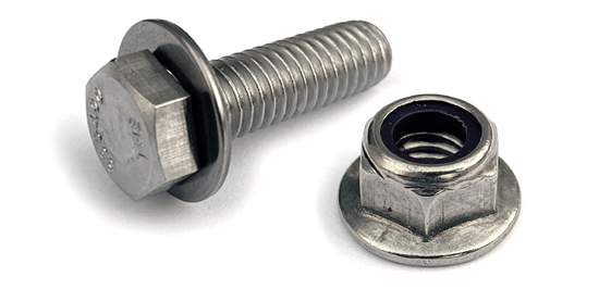
|
|
|
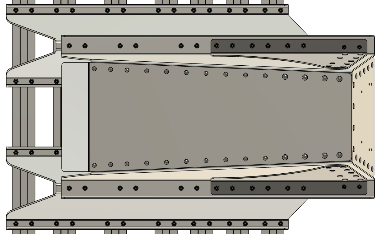
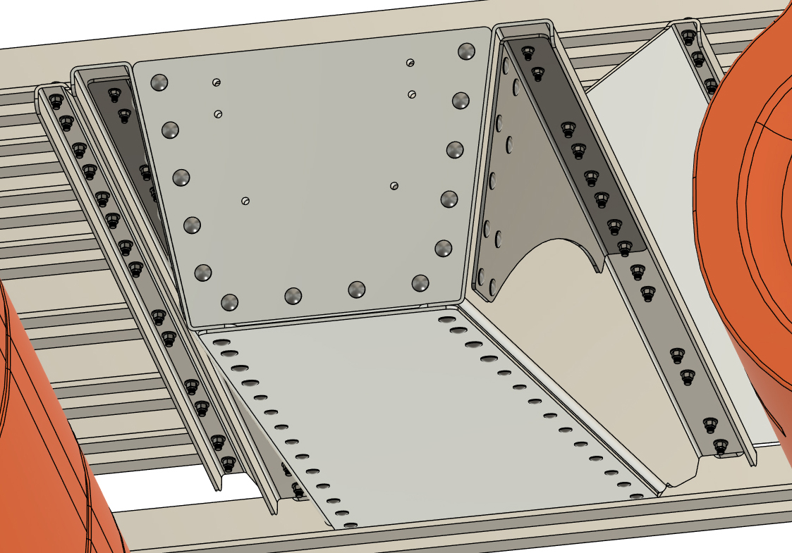
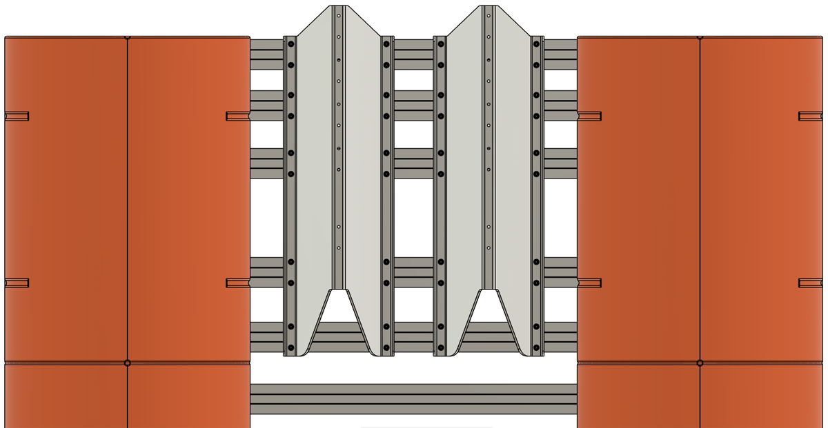
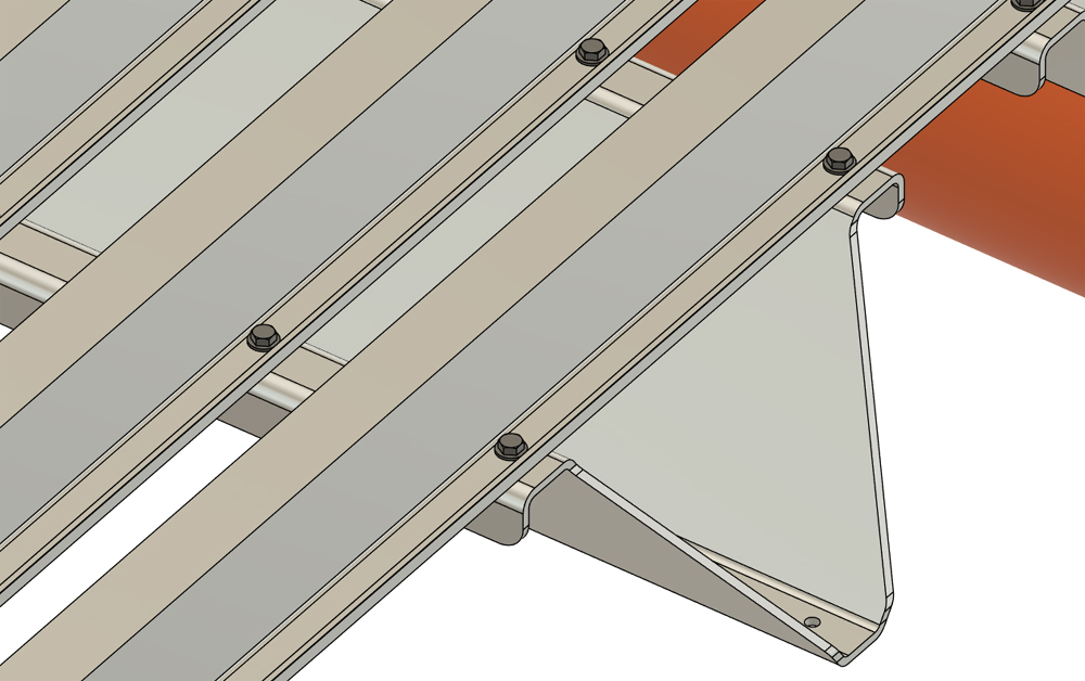
30 HP TRANSOM SYSTEM INSTALLATION
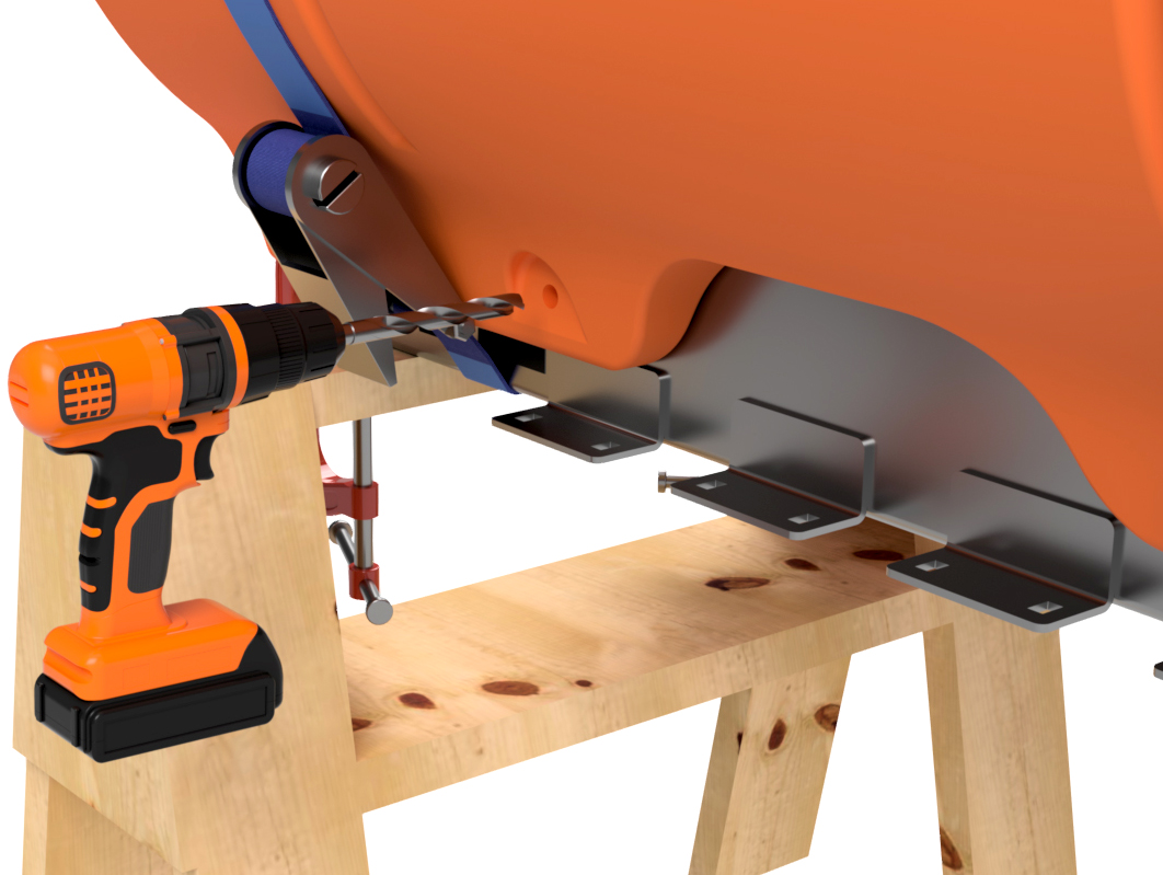
STEP 1 Select eight of the 3/8" x 1 1/4" hex bolts, flat washers, and flange lock nuts. Insert a bolt with a flat washer into the frontmost and rearmost 4 bolts holes in your "Rear Set" crossmembers. With the 8 bolts hanging down through the holes, position the two drop brackets so that the bolts hang through the frontmost and rearmost holes as shown. If working alone, a ratchet strap can hold brackets in position. Please note that the drop-brackets taper outward beyond the rear of the deck as shown.
Install a flange lock nut with LocTite applied to the threads onto each of the bolts hanging through the drop-brackets. Tighten the nuts and bolts just enough so the brackets can still wiggle. Install the same hardware through the remainder of the Rear Set crossmembers and upper flanges of the drop-brackets. Leave the hardware a bit loose for now and DO NOT FULLY TIGHTEN THE NUTS AND BOLTS YET.
|
|
|
30 HP TRANSOM SYSTEM INSTALLATION
STEP 2 The transom gets bolted to the drop-brackets with the same hardware as in the previous step. Just as before, make sure to apply LocTite to the nuts before installation.
Insert a 3/8" x 1 1/4" bolt with flat washer through the rearmost and frontmost central bolt hole of each of the drop-brackets. Lift the transom up against the drop brackets and line up the hanging bolts with the rearmost and frontmost bolts holes in the top of the transom. Just as in the prior step, loosely install lock nuts with LocTite applied. Mostly tighten the bolts so the transom can still wiggle. Install the same hardware through the remainder of the bolt holes in the drop-brackets and transom. Hand-tighten every mounting bolt and nut for the transom and drop-brackets and then fully torque every one of the 3/8" bolts to 55 foot pounds. DO NOT TORQUE BEYOND 55 FOOT POUNDS. Just as before, draw a line on every bolt with a marker after you fully torque it. After torquing every bolt to specification, visually check that you did not miss any. Fully tighten and torque all the nuts and bolts that fasten the Rear Set crossmembers to the pontoon assemblies (55 foot pounds). Draw the lines as before to indicate that you torqued each nut and bolt. Inspect that all your crossmember bolts have been torqued and your large barge frame, floats, and transom system is now complete!
|
|