
|
603-630-5658
|
|
tinypontoonboats@gmail.com
|

|
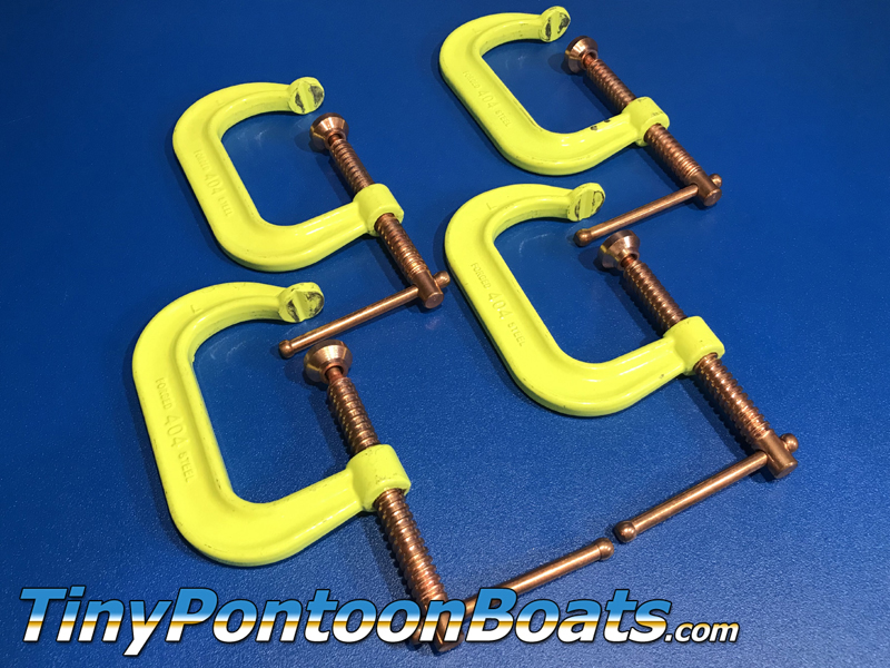
REQUIRED TOOLS
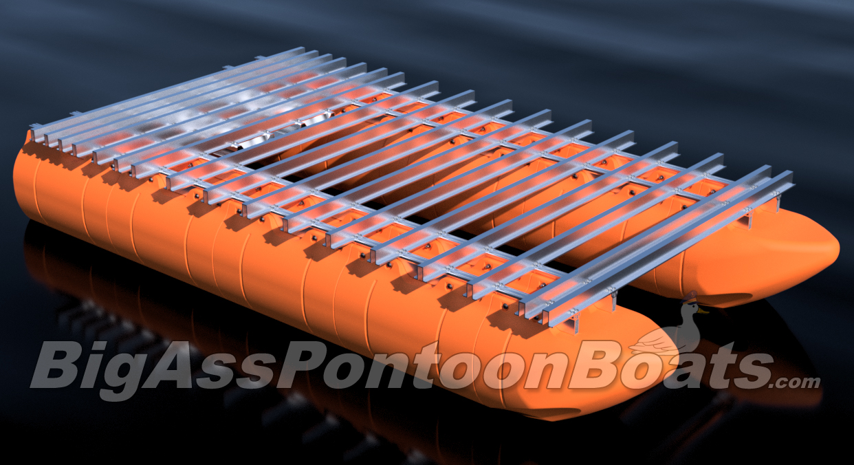
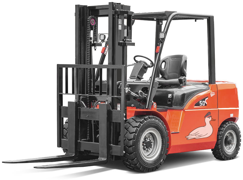
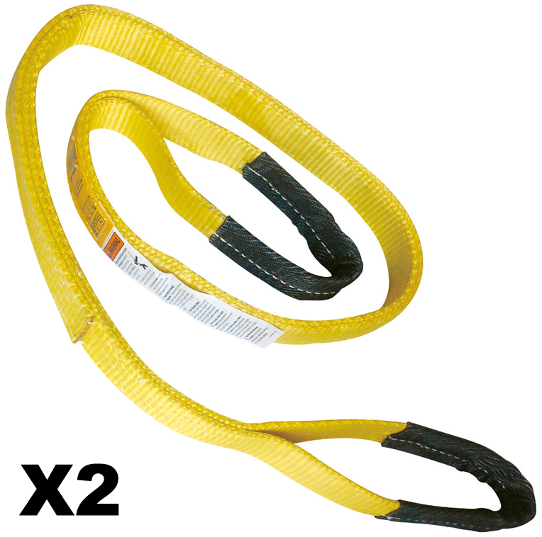
The pontoon and frame system assembly for our full aluminum frame large barge sytems with 36" floats is simple in concept and requires basic tools, a few specific tools, proper lifting equipment, and at least a 2-person team to complete safely. Even our shortest large barge system has pontoon assemblies that land at almost 700 pounds each, so this large-scale system requires a forklift or other lifting equipment to safely assemble pontoons and then move the completed vessel. Failure to be properly equipped for the task of assemby can cause risk of bodily harm, for which Tiny Pontoon Boats is not responsible. Don't underestimate the scale of what you are about to build! As our website states, you're building a Big Ass Pontoon Boat!
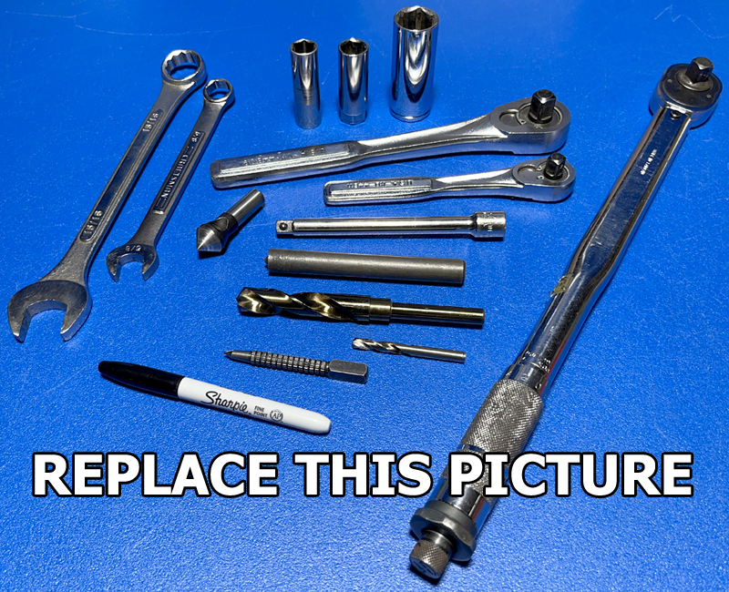
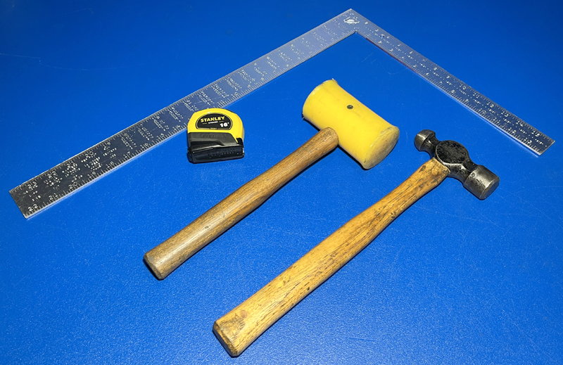
Below we have provided a list of everything that you'll need, as well as part numbers and links to where you can get the specialized tools from McMaster, which is a reasonably priced industrial supplier. Click on the part number to view the item on the McMaster website. Many customers will already have the majority of these tools, if not all of them. Many of these tools should be stocked at your local home supply or hardware store as well.
|
|

|
STEP 1
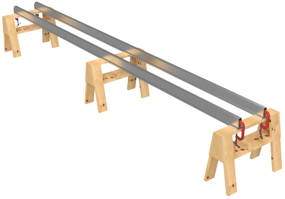
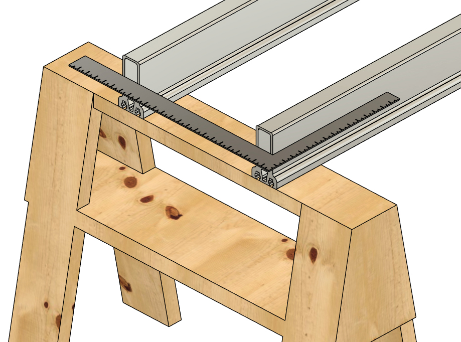
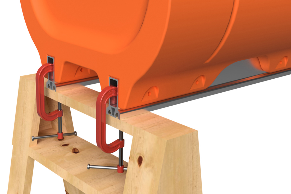
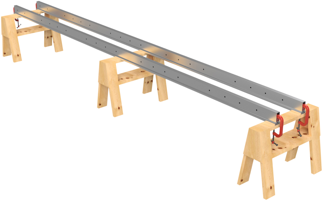
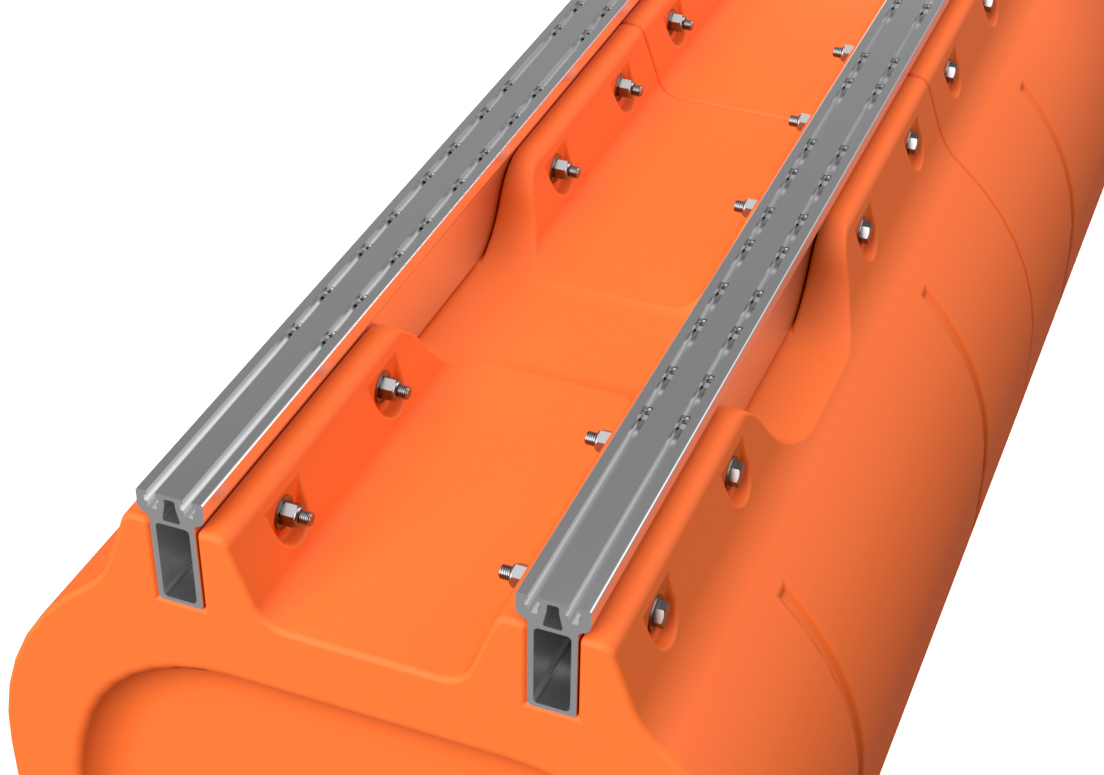
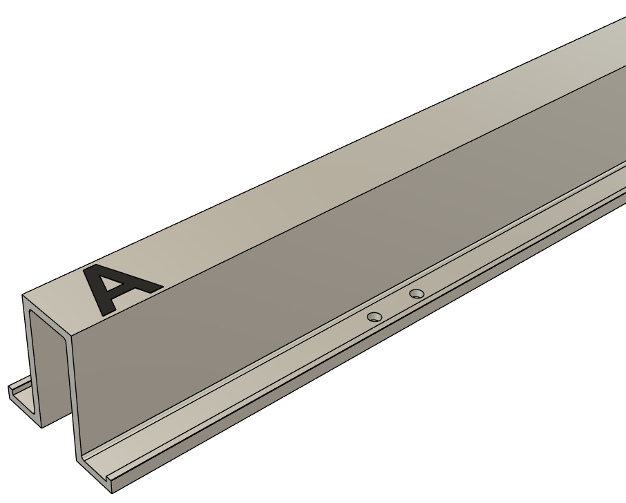
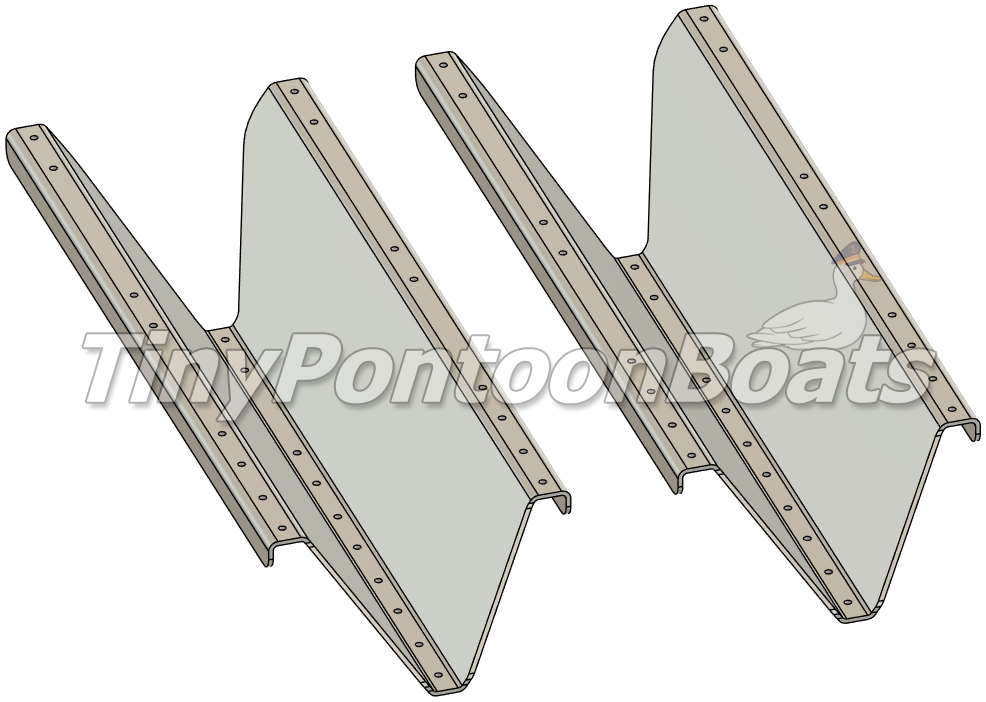
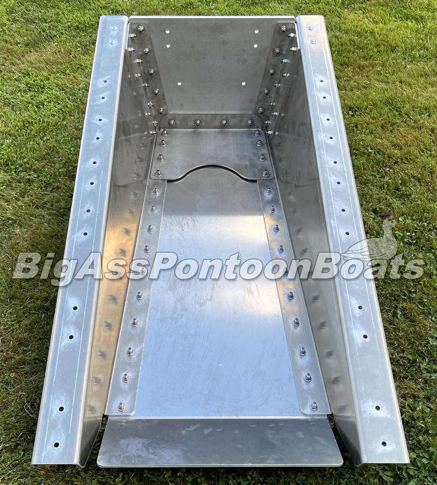
Place two of the pontoon Main Beam extrusions from your frame kit across two or more saw horses. Longer barge systems will require 3 or more saw horses. The Main Beams are the aluminum tubes that have a "T" shaped cross section with two slots on the top. Position the Main Beams so that the slots face down and are about 16" on center. Use a square to ensure that the ends are even. Clamp the two frame members to your saw horses.
NOTE:
|
|
|
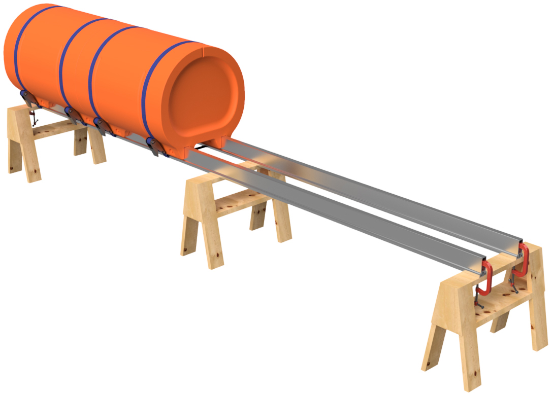
STEP 2
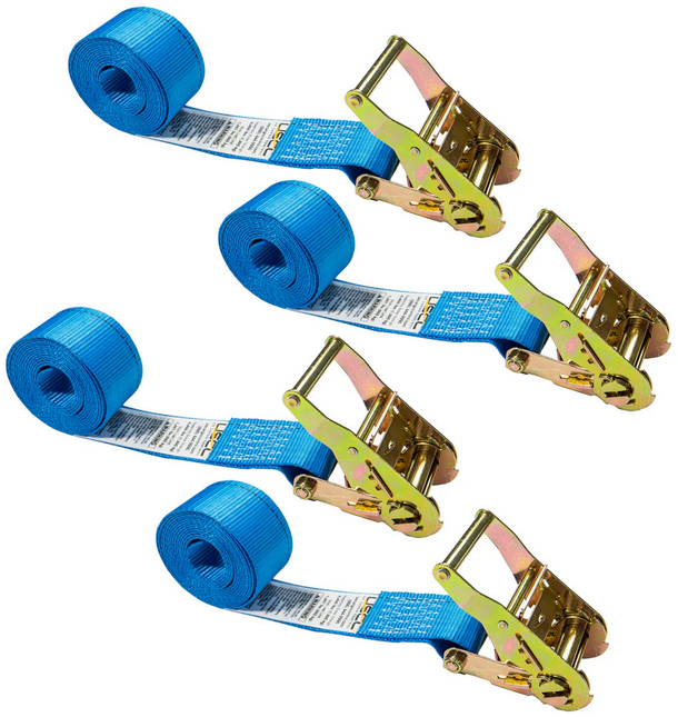
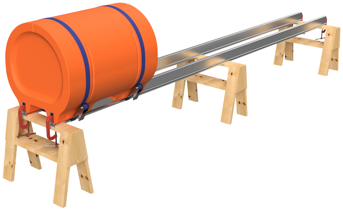
Place one of the straight floats (blunt end floats) on an end of the Main Beams. You may have to adjust the spacing of your Main Beams. Tap the float into position so that the end of the float is even with the end of the main beams. A rubber or plastic hammer can be used for this. Place a ratchet strap around the float and the Main Beams to temporarily hold the float in position and ensure that the float is properly seated on the frame members.
|
|
|
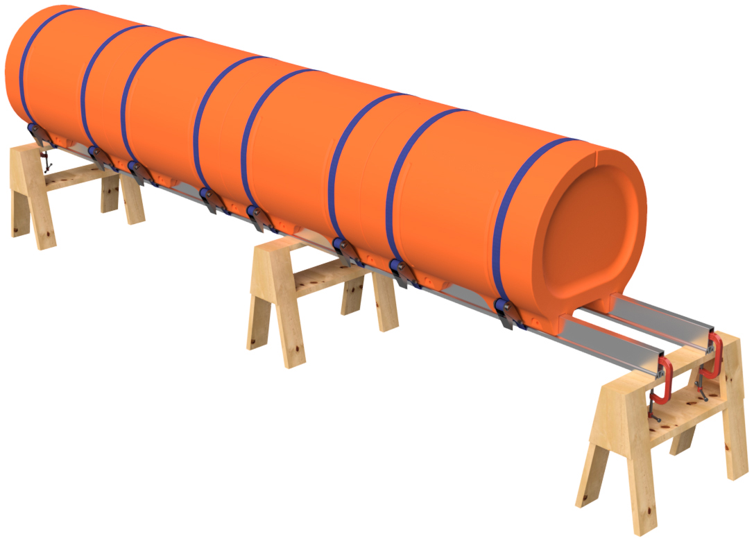
STEP 3
Place the remaining straight floats for the pontoon assembly onto the Main Beams and install ratchet straps around each float. When placing the floats on the Main Beams, tap them securely against the previously installed float. If you have to hit the float hard to adjust the placement, place a scrap of flat wood across the Main Beams and against the float and then you can use a larger hammer to make the needed adjustment. Verify that the first float is still even with the end of the Main Beams and adjust as necessary. Verify that your straps are secured.
|
|
|
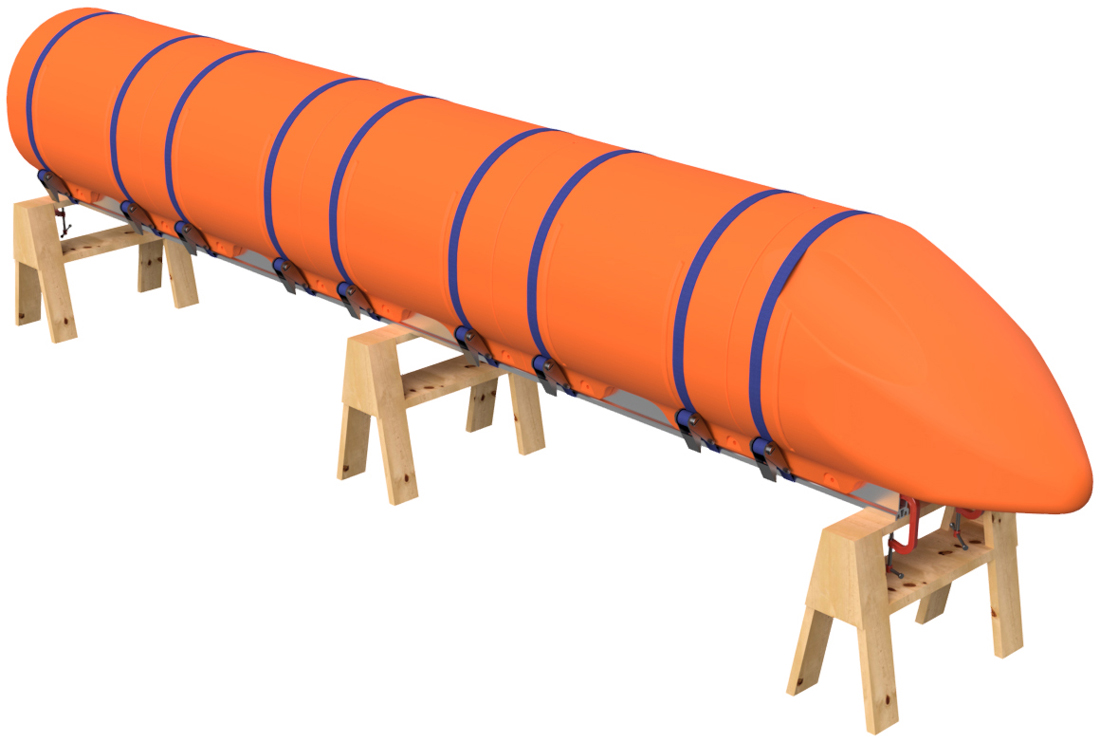
STEP 4
Place a nose cone float on the front of the pontoon assembly as shown. Due to the shape of the nose cone, you will only be able to install one strap. Make sure that the nose cone float is securely butted against the adjacent straight float section.
|
|
|
STEP 5
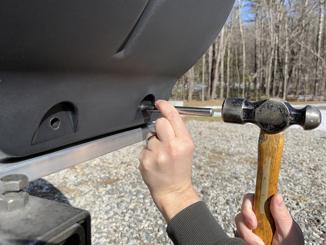
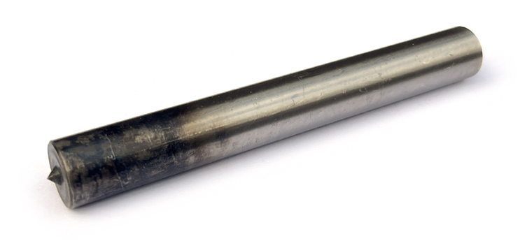
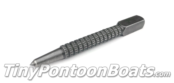
Using a 5/8" transfer punch, go down both sides of both sets of mounting channels on the plastic floats and use the punch with a hammer to mark EVERY bolt hole position through the molded-in bolt holes in the floats. You don't don't have to be gengle with this operation and you can give the punch a healthy smack! You will have to do this from both the outside set of holes and the inside set of holes. This means that you'll have to go under the pontoon assembly on your saw horses to mark the inner holes. It's inconvenient, but 100% necessary.
PRO-TIP: The transfer punch can be a tight fit in the molded-in holes of the floats. This means that they can be a bit tough to pull out of the hole after making your mark. We like to either clamp a set of locking pliers onto the punch or weld on a piece of round bar to act as a handle, which allows you to twist while pulling out the punch. We find it MUCH easier to pull the punch out of the hole with the "handle" attached.
|
|
|
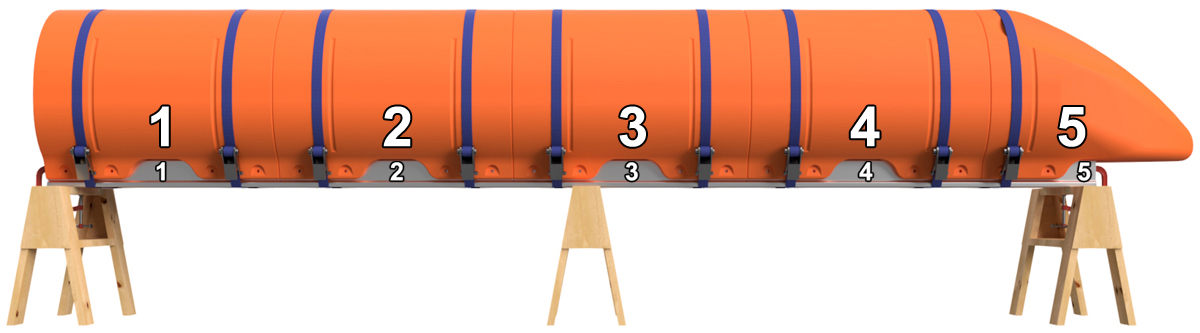
STEP 6
Remove the ratchet straps. Before removing the floats, number the positions of the floats on the Main Beams as shown. Number the floats and Main Beams on both sides of the pontoon assembly. For instance, if you're building a 20' long pontoon, you'll want to label position 1, 2, 3, 4, and 5 on one side and 6, 7, 8, 9, and 10 on the other. This ensures that you don't mix up the positions of the floats after you drill holes. You can use a piece of masking tape to write on or you can use a marker to write on the floats and Main Beams. If using a marker, lacquer paint thinner will remove the ink after assembly, and the paint thinner will not hurt the plastic or the aluminum. Remove the floats and unclamp the Main Beams from the saw horses.
|
|
STEP 7
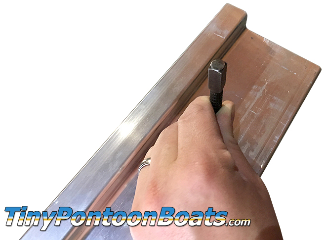
Using a standard center punch, make the marks you made with the transfer punch in step 5 more pronounce. This will make the holes easier to drill in the next step.
|
|
|
STEP 8
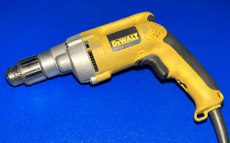
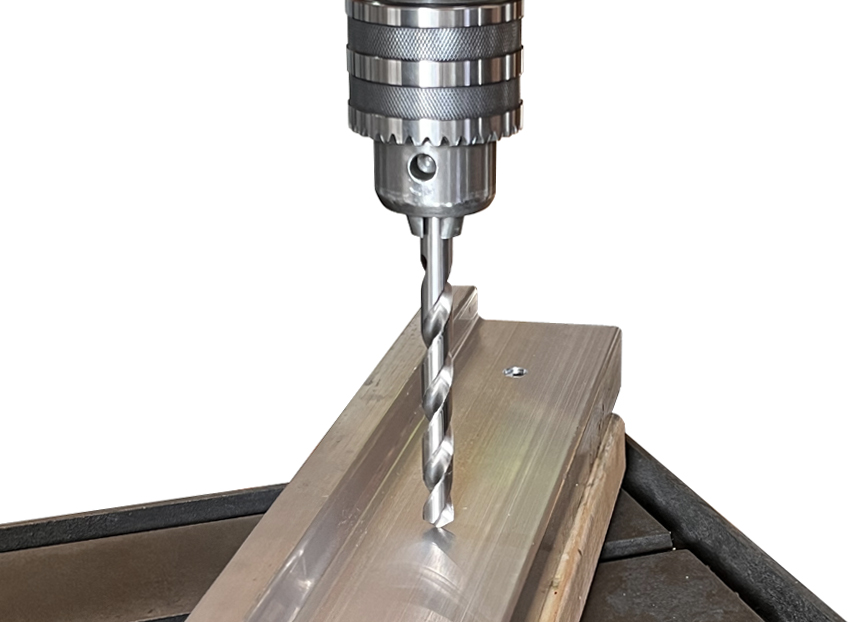
Using a SHARP (prohibits wandering of the bit) 1/4" diameter drill bit, drill through ONE WALL of each Main Beam at each marked position. DO NOT drill all the way through both sides of the Main Beams during this operation. Drill through every marked position on ONE SIDE of each part, flip it, and drill through every marked position on the other side. After drilling all the 1/4" holes in both Main Beams, use a 5/8" diameter drill bit to drill through every 1/4" hole. Once again, only drill through one wall at a time for each hole position.
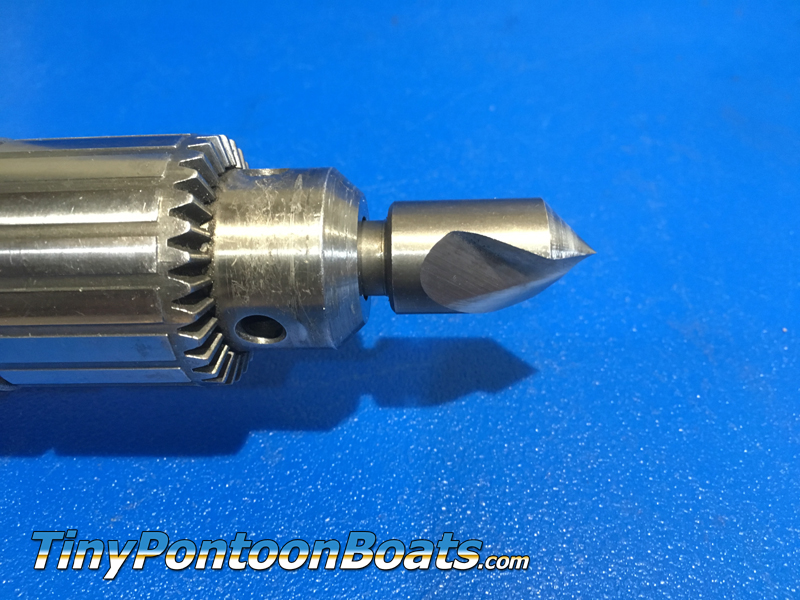
For this operation, you can use a hand-held drill, but we find it much easier and quicker to use a drill press. If you have a drill press, you will need to use a spacer block, such as a piece of 2" x 4" lumber, to make the material surface level, as well as a stand to hold the loose end of the part. A helper sure makes this task easier as well since these parts are big and hefty. If using a hand-held drill, be careful to keep the drill bit perpendicular to the surface you are drilling through. You can't undrill holes, so take your time. After drilling the holes, they must be deburred. We like to use a countersink drill bit for this, but a little bit of sand paper or a file will do the trick as well.
|
|
|
STEP 9
Clamp the main beams back onto the saw horses in the same orientation as before and place the floats back onto the main beams, matching up the numbers you marked in step 6. Place the ratchet straps back over the floats and tap the floats into position so that the holes line up. DO NOT INSERT THE BOLTS YET.
|
|
|
STEP 10
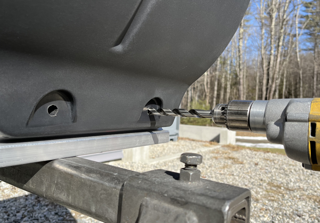
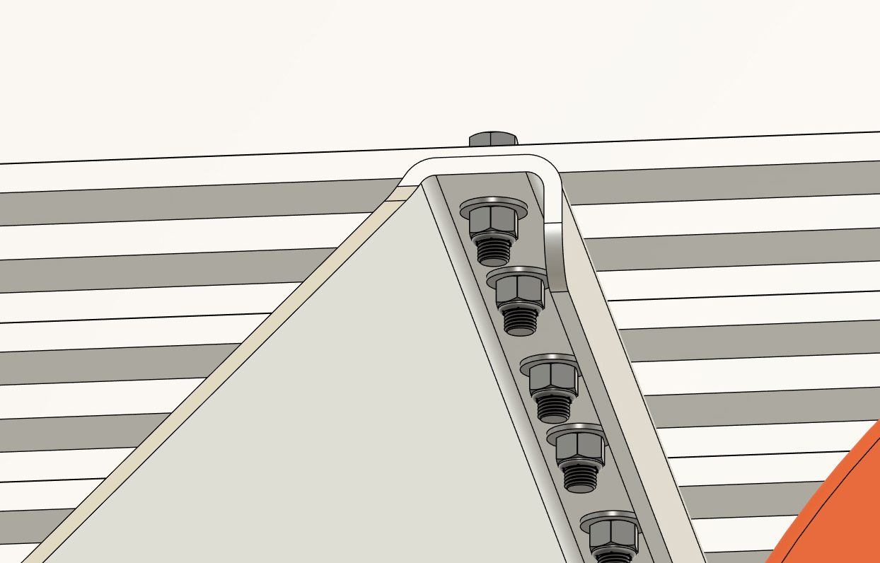
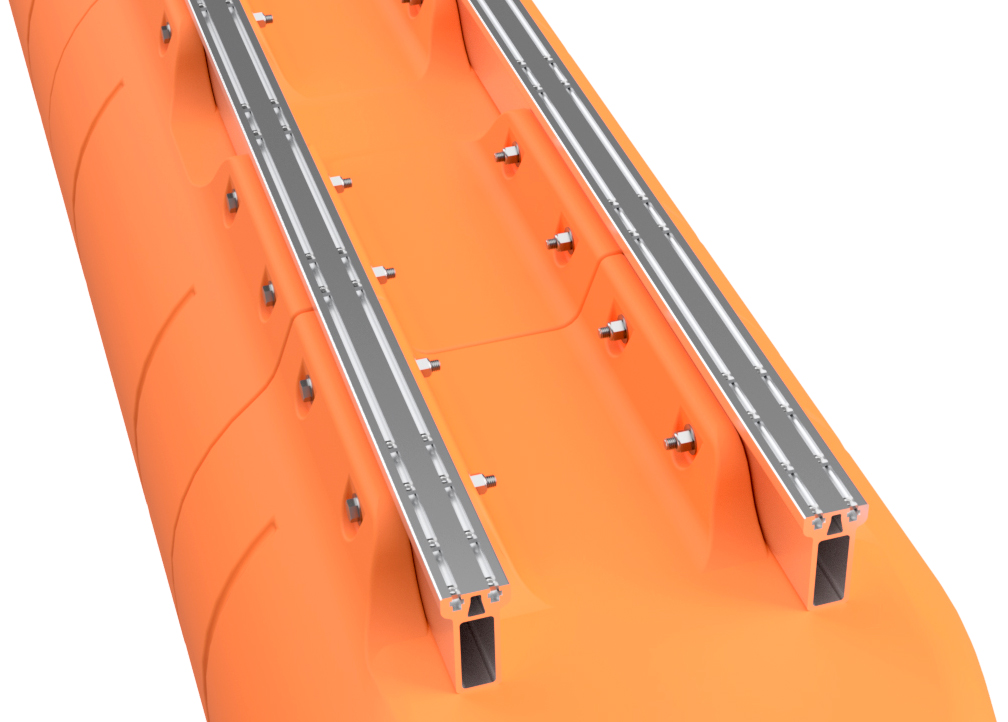
With a 5/8" drill bit mounted in your hand-held drill, start at the back end of the pontoon assembly and drill through one of the the rearmost bolt holes. Drill all the way through both sides of the Main Beam on that side of the float. You will be drilling inward from the side of the float. When doing this, go slowly, as your drill bit should only be clearing chips and verifying hole alignment, not drilling a new hole.
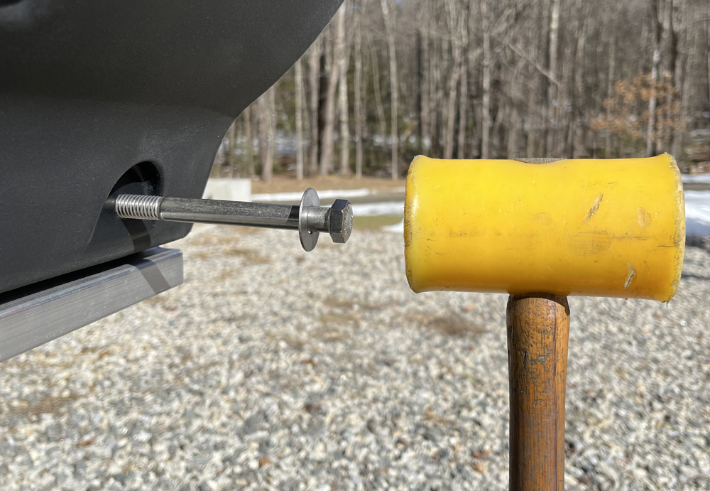
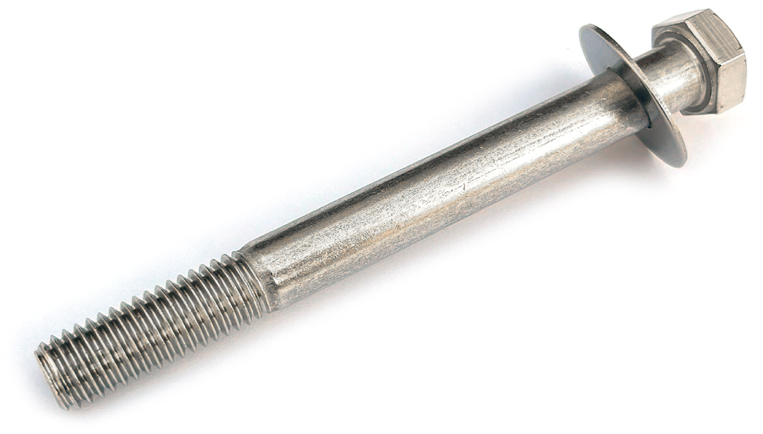
Insert one of the 5/8" x 6-1/2" hex bolts with a 5/8" flat washer from the outside position, and tap it through the hole with a hammer. We prefer to use a plastic hammer for this. Drill through the next hole and insert a bolt with washer. Do this on both sides of the pontoon assembly until every float has bolts installed through each hole on both sides of the float. DO NOT INSTALL THE NUTS YET.
|
|

|
STEP 11
Remove the ratchet straps and flip the pontoon so that it's right-side-up. Place it on the floor or flat ground.
LIFTING, ROTATING, AND LOWERING THE PONTOON ASSEMBLY TO THE FLOOR/GROUND REQUIRES USE OF A FORKLIFT, OR OTHER LIFTING EQUIPMENT, AND LIFTSTRAPS TO SAFELY COMPLETE THE PROCEDURE. DO NOT ATTEMPT TO REMOVE THE FLOAT FROM YOUR SAWHORSES BY HAND AND DO NOT ATTEMPT TO COMPLETE THE REMAINDER OF THIS STEP WITH THE FLOAT ON YOUR SAW HORSES. YOUR PONTOON ASSEMBLY IS HEAVY AND CAN CAUSE BODILY HARM IF IT WERE TO FALL. When we build boats at Tiny Pontoon Boats, we place the pontoon assembly onto pieces of scrap carpeting or rubber matting (horse stall matts are great to have around!) on our shop floor. The floats are tough, but we try not to beat them up before they reach the water. Using a rag, remove any chips from the exposed threads of the bolts you just inserted through the floats. Place 5/8" flat washers over each of the bolts. DO NOT INSTALL THE NUTS YET. Using the included LocTite (blue medium strength Loctite type 242), apply a bit of the thread locker to each of the bolts. Your kit has more than enough to get through assembly of your pontoons, so don't be stingy! You'll want to make sure that you have LocTite all around the bolt threads for each bolt. The Loctite lubricates the threads, makes the nuts more secure, and is 100% required. DO NOT SKIP THIS STEP. Thread 5/8" lock nuts onto each of the bolts and tighten the nuts until the mounting flanges on the floats start to flex inward. We do not have a torque specification beyond this. Wipe off the excess LocTite with a rag. 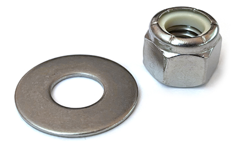 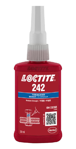 |


|
|
STEP 12
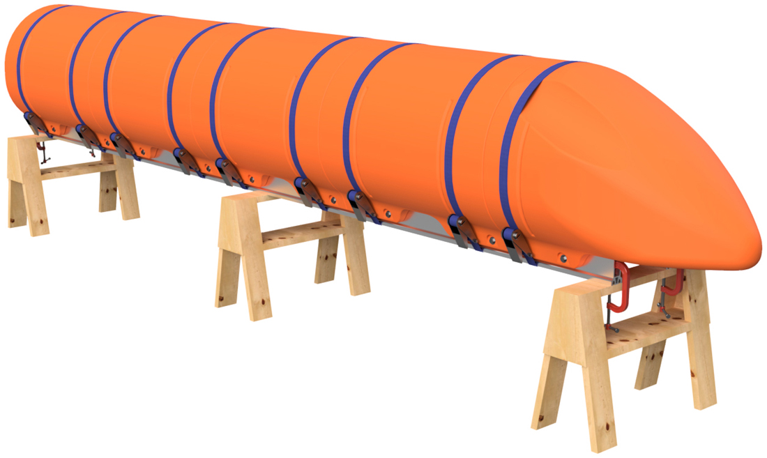
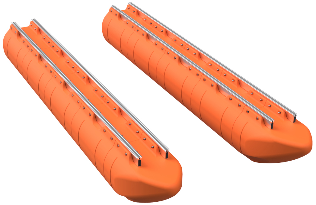
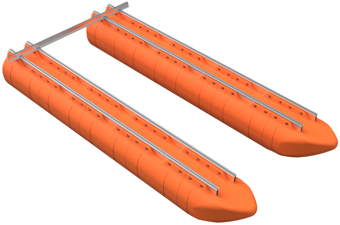
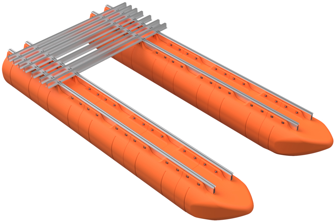
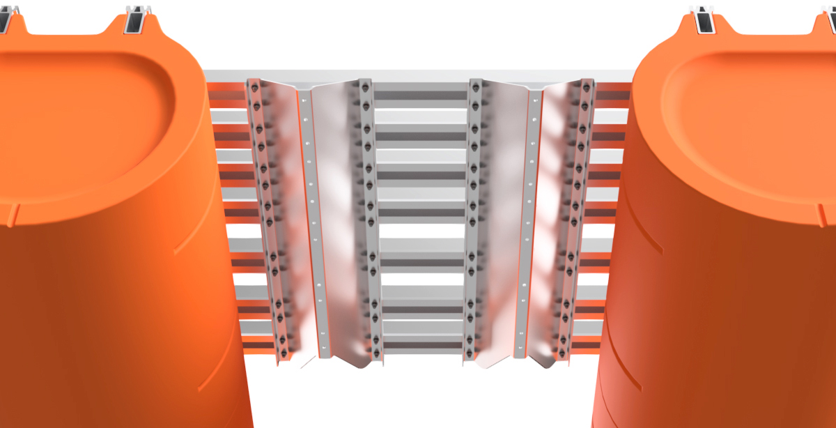
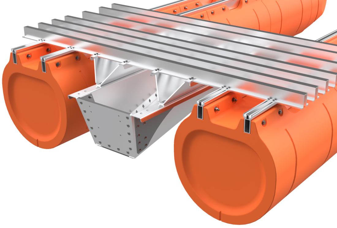
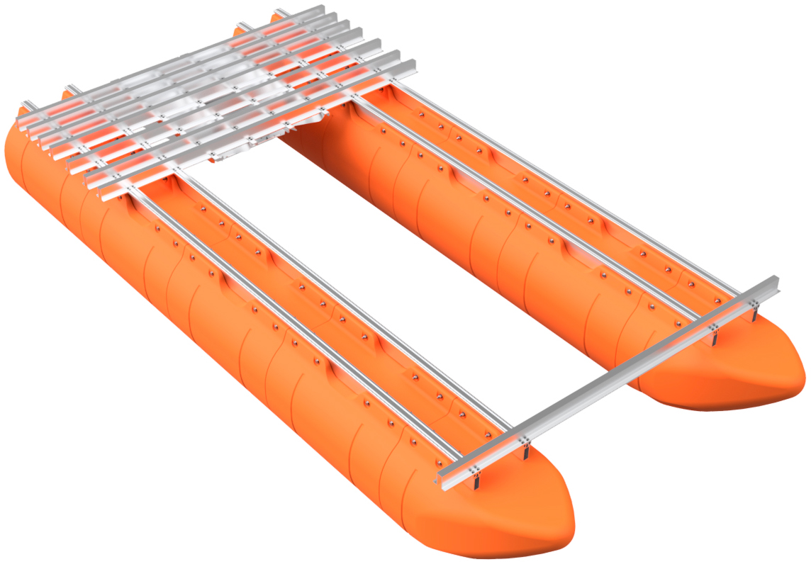
Place the completed pontoon aside and repeat steps 1 through 11 to build your second or third pontoon assembly/assemblies (3 assemblies for tri-toon barges). Place your pontoon assemblies on a flat surface so that the outer floats are about 66" apart on-center for 8.5' wide barges, 84" apart on-center for 10' barges, and 108" apart on-center for 12' wide barges. If you are building a tri-toon, place that third pontoon assembly between the outer floats when completed as well.
|
|
|
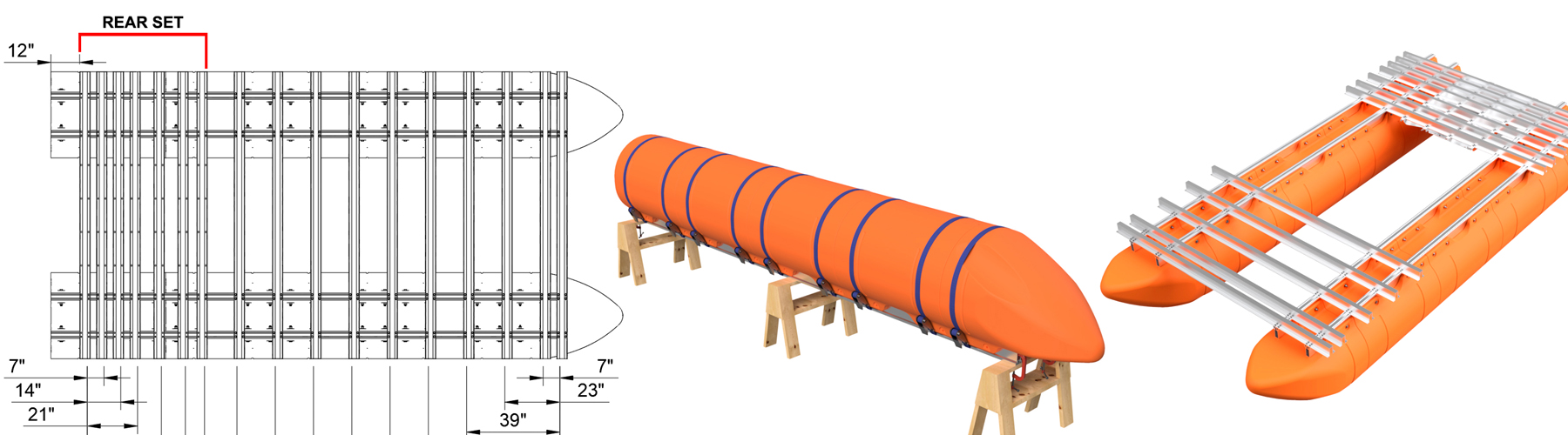
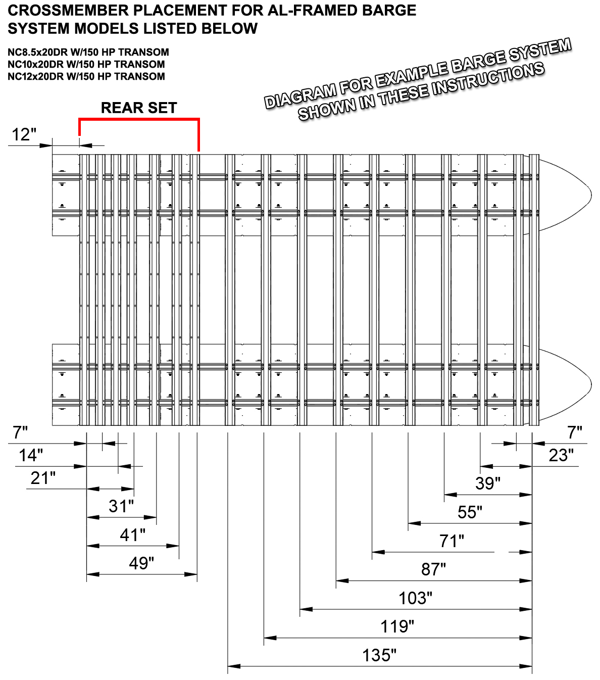
CROSSMEMBER PLACEMENT DIAGRAMS:
Moving forward, you will have to reference the crossmember placement diagram applicable to your specific barge kit. At this time, we do not have diagrams for every standard option on our site, but the applicable diagram will be provided after your purchase. If possible, print your required diagram or have it handy on a mobile device as you will need to reference it throughout the remaining assembly. The diagram is particularly important to follow if you purchased additional accessories designed to mount to specific crossmembers on your barge. Be careful and double-check all crossmember placement before fully tightening bolts from this point forward.
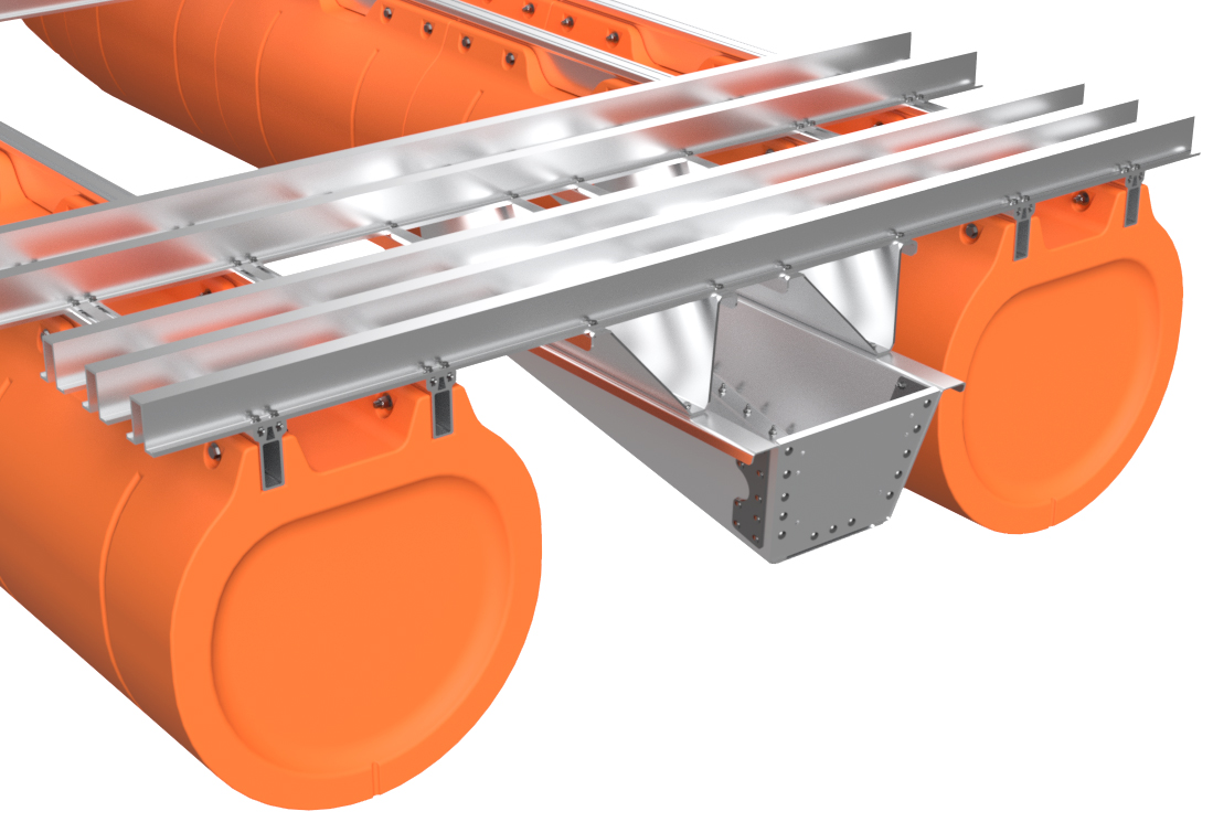
If you purchased a transom system with your barge kit, your diagram will state "Rear Set" for the rearmost 5 to 7 crossmembers. These crossmembers will have holes pre-machined for mounting your transom system and go at the rear of the boat. Please note that some dual-row pontoon systems (2 pontoon assemblies) have the "Rear Set" crossmembers placed ahead of the end of the pontoon assembly Main Beams. This is intentional in our design and helps balance the completed vessel. If you are building a triple-row barge (tri-toon) with our large transom, there will also be a "FRONT Rear Set" crossmember (see example diagram here). This crossmember both attaches to the front of your transom droip-brackets and the center pontoon assembly. If you did not purchase a transom system for your barge kit, every crossmember is identical. |
|
|
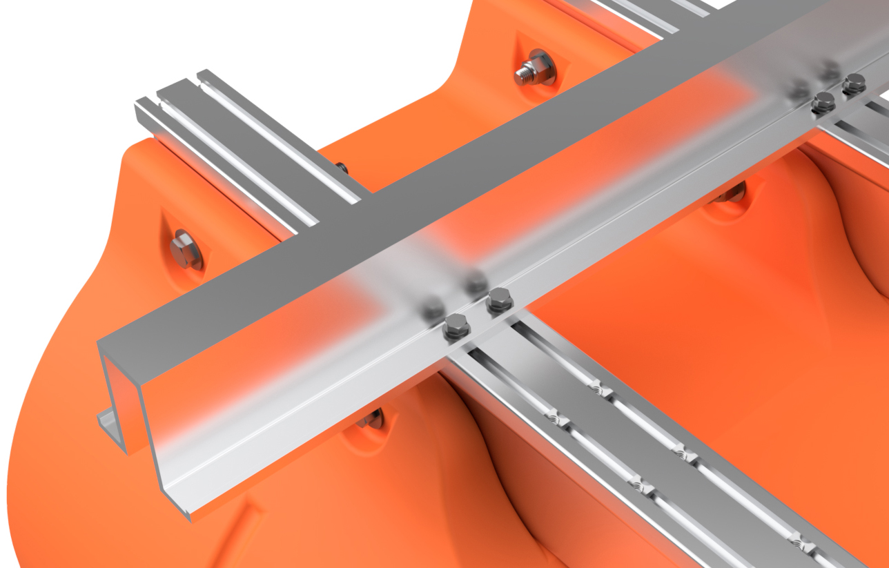
STEP 13
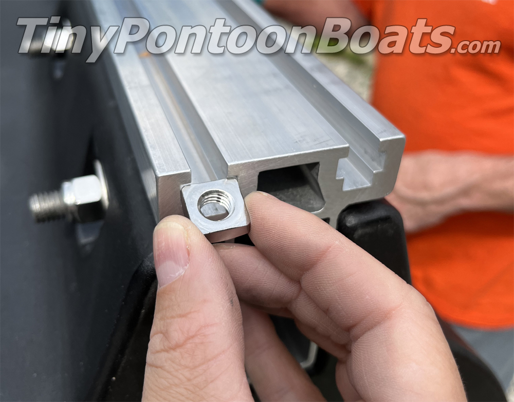
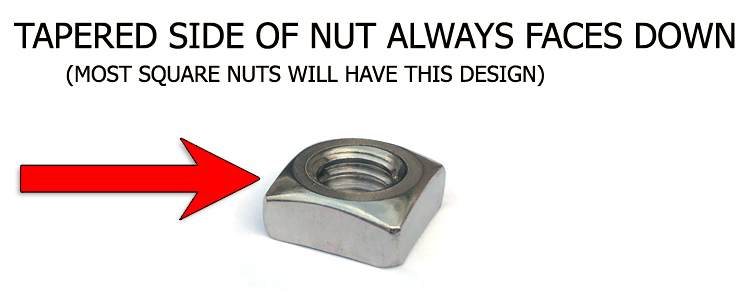
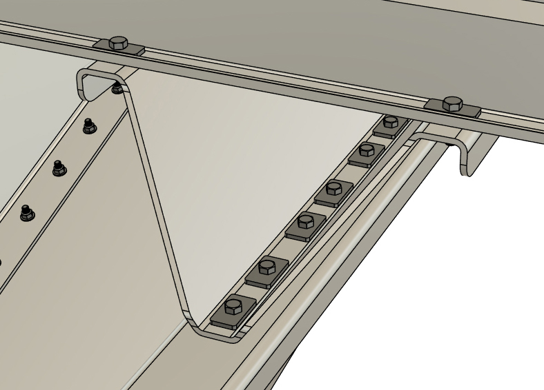
Each hat channel crossmember requires 4 sets of nuts, bolts, and washers for each pontoon assembly Main Beam connection point. Slide 2 square nuts into each Main Beam slot for each "rear set" crossmember shown on your crossmember placement diagram. Position the nuts in the approximate locations of each "rear set" crossmember on your diagram.
|
|
|
FRAME & ACCESSORY FASTENER TORQUE SPECIFICATIONS
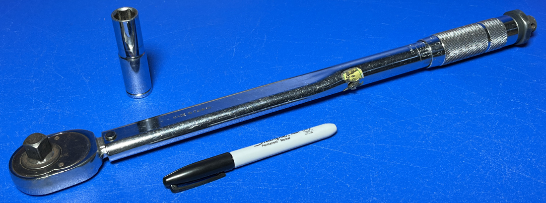
Each of the 3/8" or 7/16" nuts and bolts installed from this point forward require the proper amount of torque to ensure that they are fastened securely and retain full holding strength. The proper torque specifications for either hardware size is listed below.
3/8" nuts and bolts: 55 foot-pounds 7/16" nuts and bolts: 60 foot-pounds From this point forward when we say to "fully torque" or "fully tighten" a bolt or nut, we are referring to the specifications above. Also, it is good practice to draw a line on the head of a bolt with a marker after it has been torqued to specification. This makes it very easy to do a visual inspection to ensure that you didn't miss any fasteners. If you do not own a torque wrench or do not want to purchase one for your assembly, many autopart stores will allow you to borrow one at little or no cost. USE OF A TORQUE WRENCH ON ALL THE FASTENERS FROM THIS POINT FORWARD IS NOT OPTIONAL. FAILURE TO PROPERLY TORQUE ANY FASTENER FROM THIS POINT FORWARD CAN CAUSE COMPONENTS TO LOOSEN CAUSING EVENTUAL SYSTEM FAILURE AND/OR SCURVY. YOU CERTAINLY DON'T WANT SCURVY. |
|
|
NOTE
Crossmembers have "A" written on one end. Be sure to place the marked ends of the crossmembers on the same side of the boat (doesn't matter which side). When the hole pattern is machined in each crossmember, this is the end that is referenced on the machine cutting the holes. Placing the "A" end of all the crossmembers on the same side of the boat ensures perfect alignment of all the mounting holes.
|
|
|
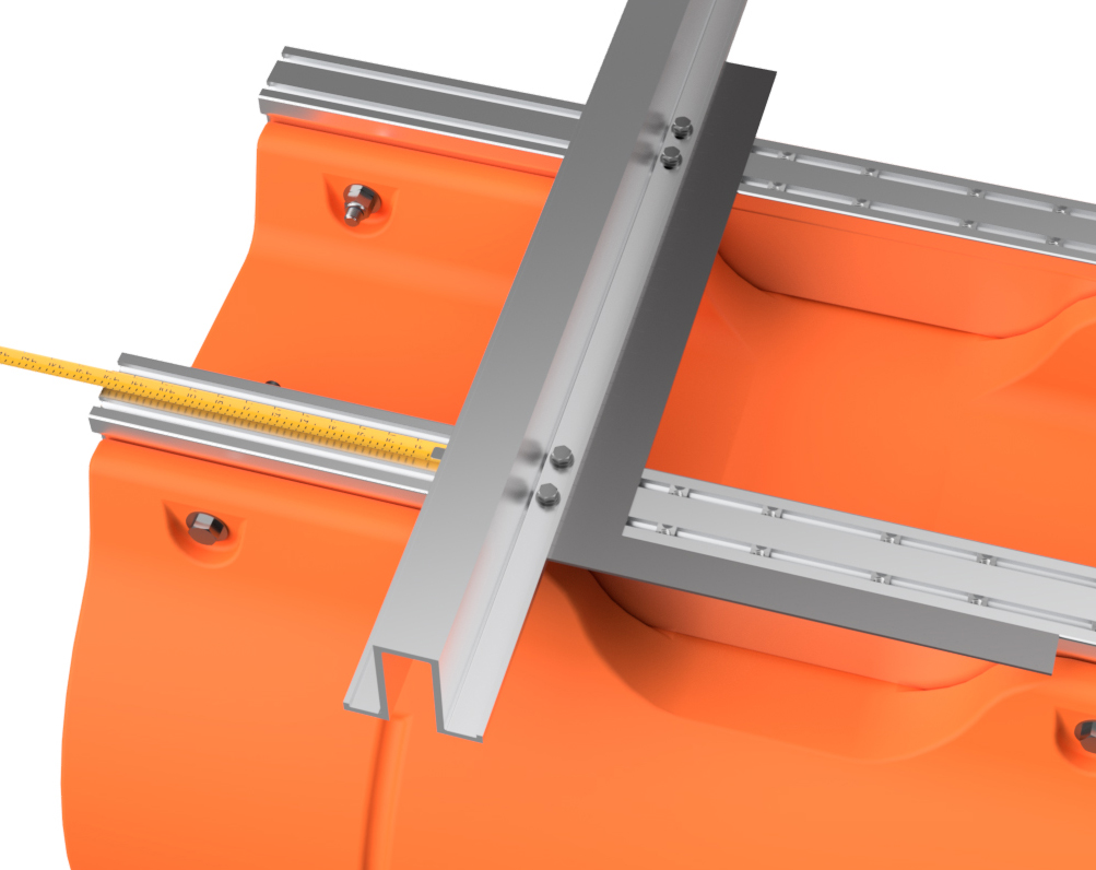
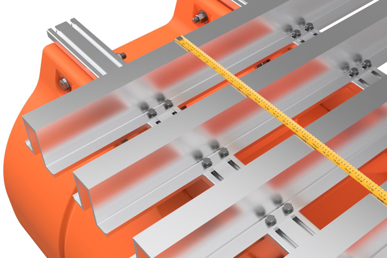
STEP 14
Loosely bolt the rearmost hat channel crossmember across your two pontoon assemblies using the 3/8" x 1" hex bolts, 3/8" lock washers, and 3/8" SAE flat washers. If you purchased a transom with your barge system, be sure to select a hat channel that has "Rear Set" written on it. Adjust the crossmember so that it is placed where your crossmember placement diagram indicates. As we are showing assembly of a 10'x20' dual-row barge with 150 HP transom in this set of instructions, and our crossmember placement diagram shows a 12" space behind the rearmost "Rear Set" hat channel, we are placing the crossmember 12" forward of the end of the Main Beams on our boat.
Double-check your measurement and use a square to ensure that one of the pontoon assembly Main Beams is square with the hat channel. Fully tighten all 8 bolts on that side of the hat channel. Adjust the opposite pontoon assembly in the same manner, ensuring that it is square with the hat channel, and install the required bolts and washers, but keep them only finger-tight for now. If you are building a tri-toon with a transom, you will not yet be bolting to the central pontoon assembly. If you purchased a system with a full-length central pontoon, bolt your hat channel to that float as well, also keeping the bolts only finger-tight. 
|
|


|
STEP 15
Loosely bolt on the remaining "Rear Set" hat channel crossmembers and place them as shown on your crossmember placement diagram. Adjust the pontoons as necessary to ensure that the rearmost hat channel is square with the main beams on both pontoons, and completely tighten the loose rearmost hat channel bolts. Leave all but the rearmost hat channel bolts loose for now.
|
|
|
STEP 16
If you DID NOT purchase a transom with your barge system, skip this step and move onto step 18.
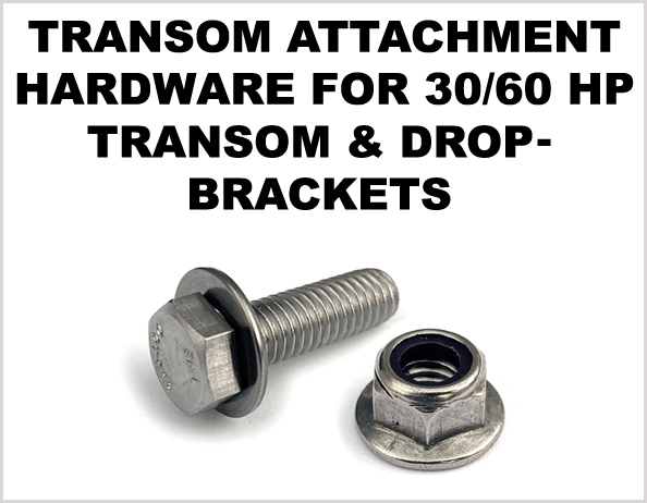
If you purchased a 30 or 60 HP transom system with your barge system, there will be a single bag in your hardware kit labeled "transom hardware" or similar. If you purchased a 150 HP transom system, there will be a separate box with multiple bags in it. We have separate simple instructions for either scenario below. 30 & 60 HP TRANSOM SYSTEMS:
Attach the drop-brackets so that they taper outward beyond the rearmost crossmember. Install 3/8" flange locknuts onto each bolt and be sure to apply some of the blue LocTite to the threads of each nut before installation. Tighten them MOST OF THE WAY so that the two drop-brackets hang, but are still loose on the frame.
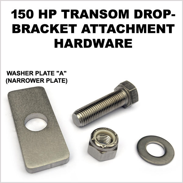
150 HP TRANSOM SYSTEMS:
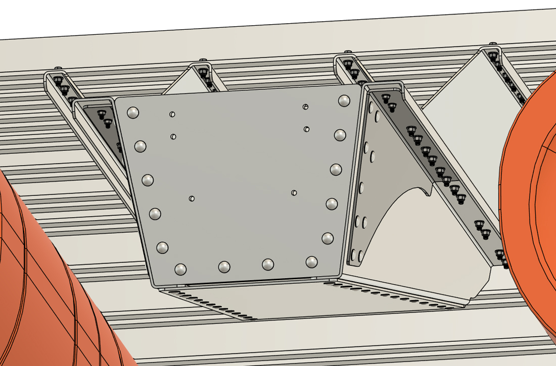
From your package of hardware, select the 7/16" x 1 1/2" hex bolts and the spacer plates labeled "WASHER PLATE A" (narrower of the two spacer plate designs). Install the bolts with the plates over them through each of the central "Rear Set" crossmember holes so that the bolts hang below the crossmembers. If you are building a triple-row barge (tri-toon), and have a "Front Rear Set Crossmember" labeled on your crossmember diagram, only the outer 4 central holes will get these bolts (the central 8 will already be used to bolt to your central pontoon assembly). Attach the drop-brackets so that they taper outward beyond the rearmost crossmember. Install 7/16" flat washers and lock nuts onto each bolt and be sure to apply some of the blue LocTite to the threads of each nut before installation. Tighten them MOST OF THE WAY so that the two drop-brackets hang, but are still loose on the frame.
|
|
|
STEP 17A
30 & 60 HP TRANSOM SYSTSEMS: SKIP TO STEP 17B BELOW FOR 150 HP TRANSOMS
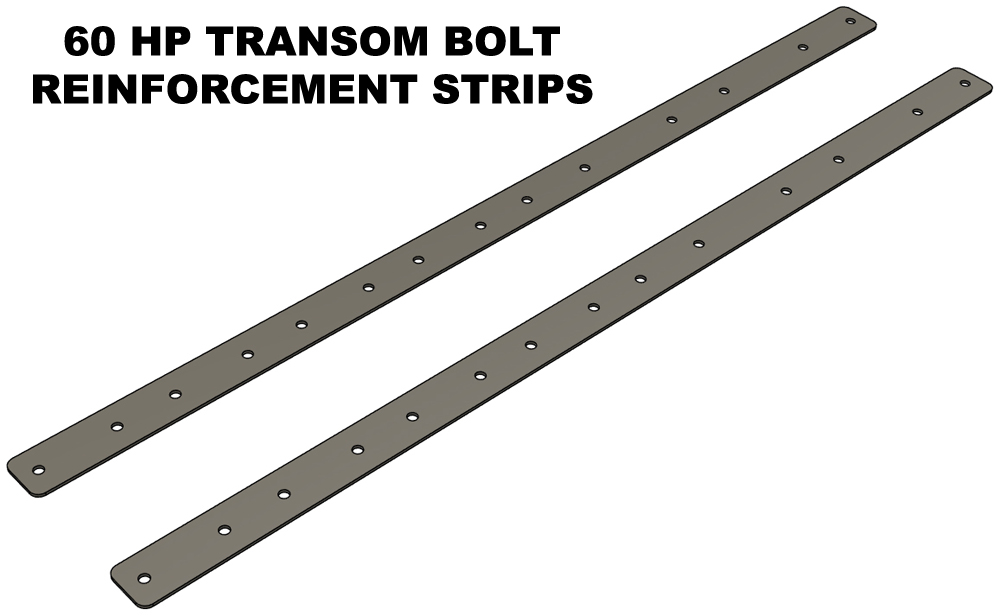
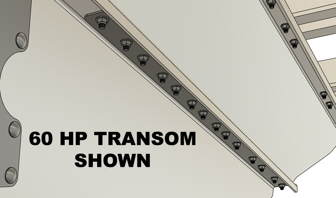
Using the same 3/8" x 1 1/4" hex bolts from your "transom mounting hardware" bag, insert bolts with flat washers through all the holes in the base of your drop-brackets. Install the transom up against the base of your drop-brackets using the hanging bolts and loosely install 3/8" lock nuts WITH LOC-TITE APPLIED to every one of the nuts before threading them onto the bolts. PLEASE BE AWARE THAT 60 HP TRANSOMS ALSO HAVE 2 STAINLESS REINFORCEMENT STRIPS THAT ARE INSTALLED BETWEEN THE LOCK NUTS AND THE TRANSOM MOUNTING FLANGES AS SHOWN (BOTH SIDES). 30 HP transoms do not use these parts. Loosely tighten all the nuts and bolts that attach through the transom. Do not fully torque the bolts yet. Now that every bolt is loosely installed, we can fully torque all the bolts that are currently loose. Follow the order of operations listed below when torquing your the bolts and be sure to draw a line on bolt heads after each nut and bolt assembly has been fully torqued to 55 foot-pounds. 1. All the bolts fastening the "Rear Set" crossmembers to the pontoon assemblies
|
|
|
STEP 17B
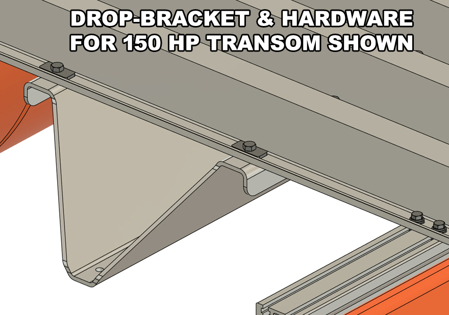
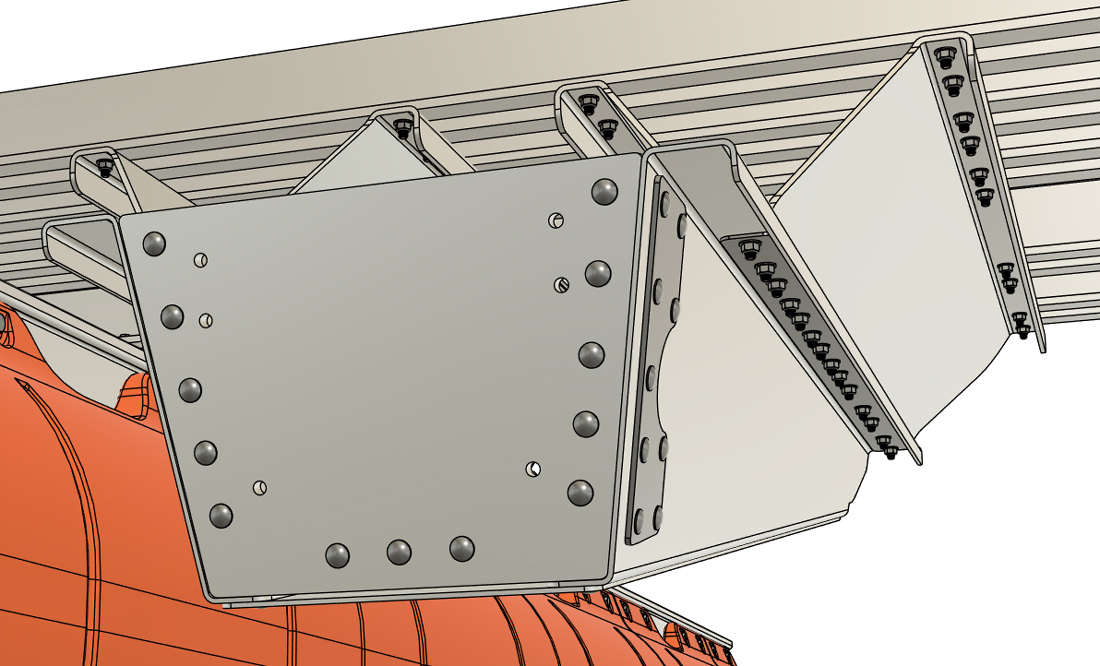
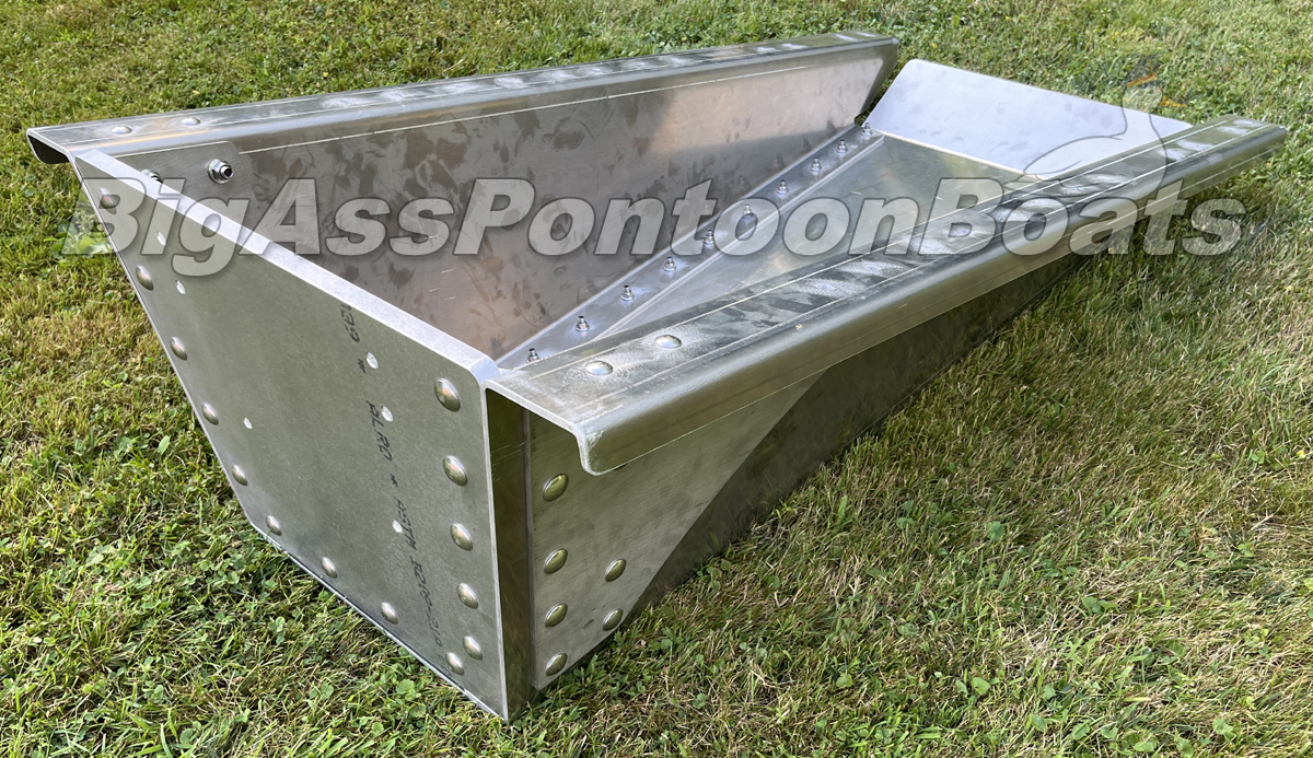
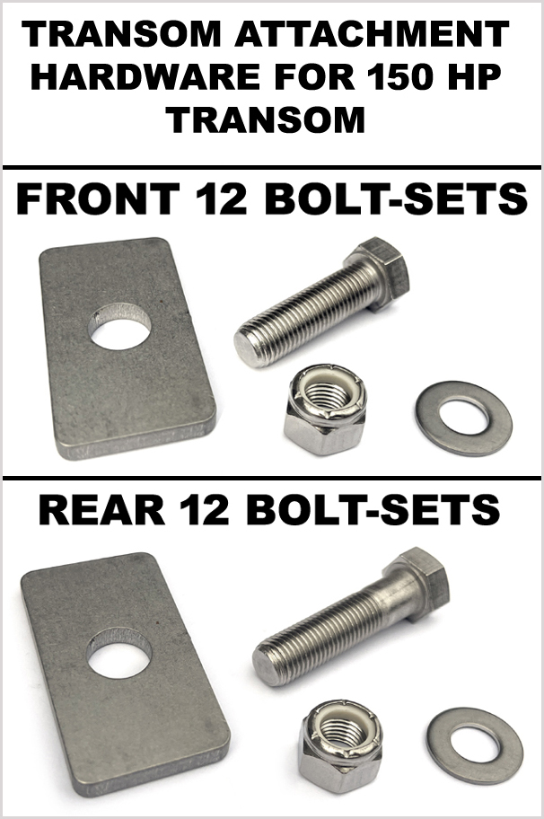
150 HP TRANSOM SYSTSEMS: Our 150 HP transom is bolted to the drop-brackets with two different length 7/16" bolts from the box of transom hardware. This size transom has a hefty 1/4" thick stainless reinforcement plate on either side that aligns with the 6 rearmost mounting holes on either side of the transom drop-brackets, so the 6 rearmost hole positions on either side of the transom require longer bolts (see picture below) than the front 6 holes on each side.
Insert a 7/16" x 1 1/2" long bolts with "Washer Plate B" through the front 6 bolt holes of each transom drop bracket as shown. Insert 7/16" x 1 3/4" long bolts with "Washer Plate B" through the reamaining 6 rearmost bolt holes of each drop-bracket. Install the transom up against the base of your drop-brackets using the hanging bolts and loosely install 7/16" flat washers and 7/16" lock nuts WITH LOC-TITE APPLIED to every one of the nuts before threading them onto the bolts. Loosely tighten all the nuts and bolts that attach through the transom. Do not fully torque the bolts yet. Now that every bolt is loosely installed, we can fully torque all the bolts that are currently loose. Follow the order of operations listed below when torquing the loose bolts and be sure to draw a line on bolt heads after each nut and bolt assembly has been fully torqued. 1. All the bolts fastening the "Rear Set" crossmembers to the pontoon assemblies (55 foot-pounds)
|
|
|
STEP 18
Referencing your crossmember placement diagram, slide groups of four 3/8" square nuts into each pontoon Main Beam at the approximate locations of the remaining hat channel crossmembers shown on your crossmember placement diagram.
|
|
|
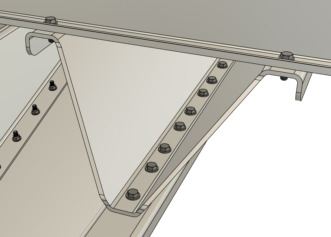
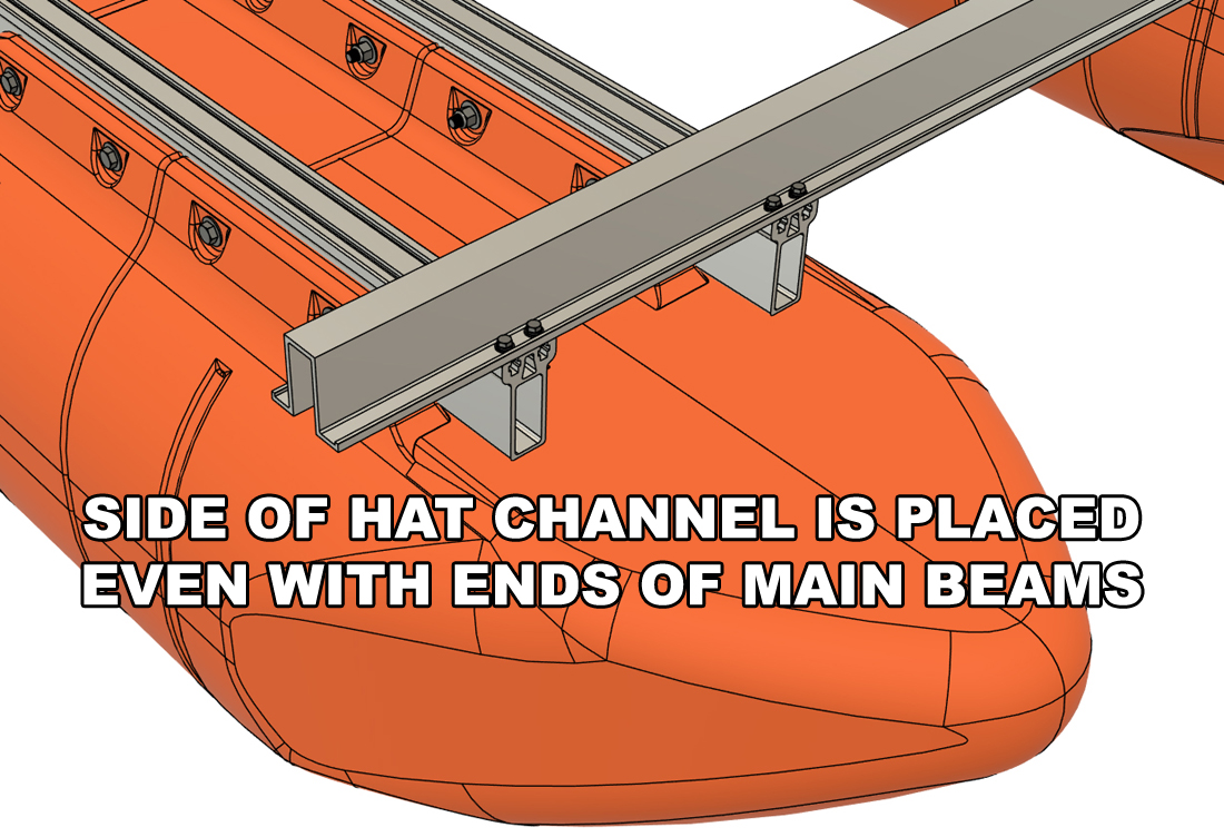
STEP 19
Place one of the standard hat channel crossmembers across the front end of your pontoon Main Beams. Position the hat channel so that its side edge is even with the ends of the Main Meams. Align the square nuts with the bolt holes and install 3/8" x 1" hex bolts with lock and flat washers as you did with the prior hat channels. Slightly tighten the bolts with your socket and ratchet, but don't fully torque them quite yet.
|
|
|
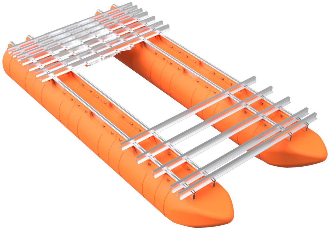
STEP 20
Working your way to the back of the boat, bolt on the remaining hat channel crossmembers. Be sure to reference your crossmember placement diagram and place your crossmembers where they are listed on your diagram. Double-check your measurements before bolting down each crossmember. As you do this, finger-tighten the bolts for now.
|
|

|
STEP 21
Working your way from back to front, one hat channel at a time, FULLY TORQUE all the hat channel bolts that you installed in the last two steps. Be sure to draw a line on every bolt that you fully torque.
Visually inspect that every frame and transom bolt has been fully torqued (will have the line drawn on it). Fully torque any bolt that you may have missed. |
|
|
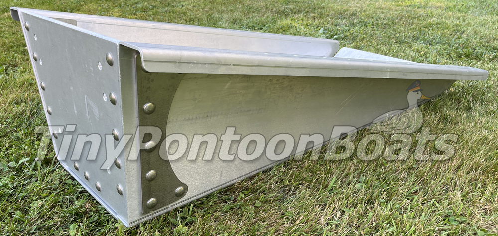
THIS PART OF YOUR PROJECT IS COMPLETE!
The frame and floats system for your Big Ass Pontoon Boat is now complete! Pat yourself on the back as you did a great job!
|